ROX1SJ680R Datasheet Deep Dive: Key Electrical Specs
According to the latest datasheet references, the ROX1SJ680R is specified as a 680 Ω ±15% metal‑oxide axial resistor rated for 1 W continuous dissipation, with a typical TCR around ±350 ppm/°C and an operating range down to −55 °C up to +155 °C — this deep dive translates those numbers into design decisions you can apply today. This article focuses on electrical specs critical to selection, thermal behavior, lab verification, and a compact application checklist to accelerate engineering review.
Background — what the ROX1SJ680R is and where it fits
Technology & mechanical overview
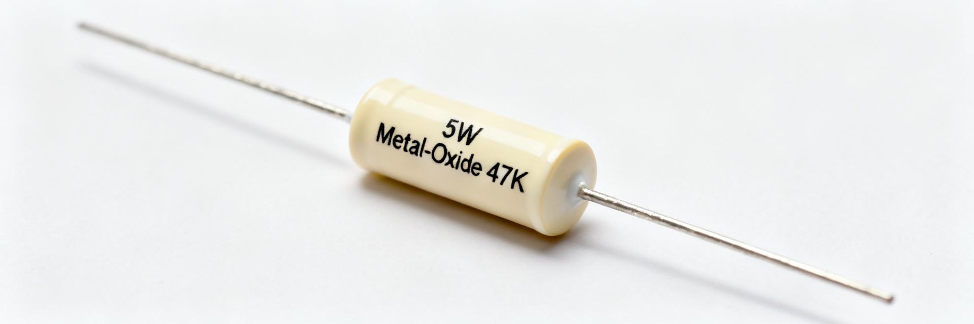
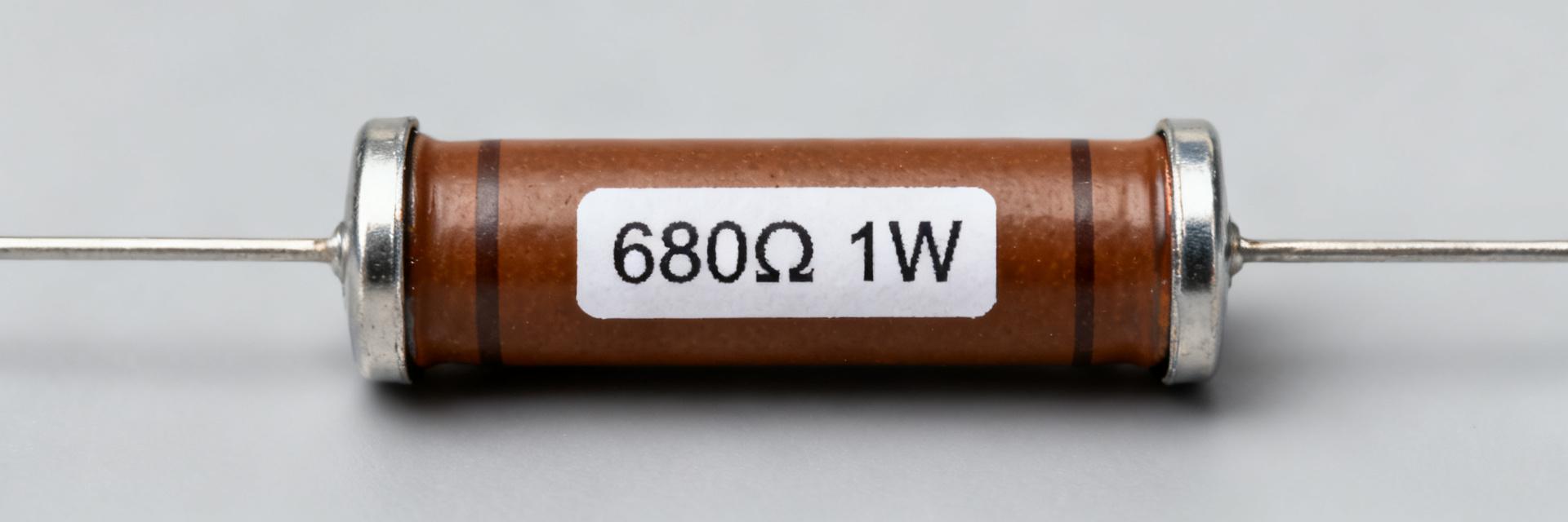
The ROX1SJ680R is a metal‑oxide composition axial resistor in a through‑hole leaded package; metal‑oxide resistors offer good stability, high pulse tolerance and flameproof behavior compared with simple carbon films. Typical axial bodies occupy modest board space and allow hand or wave soldering; lead form and trimmed dimensions affect PCB standoff and heat transfer, so designers should consult the exact dimension table in the datasheet when planning footprints.
| Spec | Typical Value |
|---|---|
| Resistance | 680 Ω |
| Tolerance | ±15% |
| Power rating | 1 W (continuous) |
| Body/lead | Axial leaded, flameproof feature (if listed) |
Typical applications and design contexts
Common use cases include general‑purpose power dissipation, bleeder/bleed resistors, snubber networks and precharge circuits where robustness matters more than precision. In each context, priorities differ: power dissipation and pulse withstand dominate for snubbers, while drift (TCR) matters for sensing or timing networks; match the application to the electrical constraints analyzed below.
Key electrical specs (data analysis)
Resistance value, tolerance and power rating — what they mean in practice
680 Ω ±15% implies a tolerance window of 578 Ω to 782 Ω; design and BOM acceptance tests should allow that spread. For power: 1 W continuous is typically specified for free‑air mounting at a stated ambient; engineers must use P=I²R and P=V²/R to size parts. Example calculations: I = sqrt(P/R) = sqrt(1/680) ≈ 38.4 mA; V = sqrt(P·R) = sqrt(1·680) ≈ 26.1 V. Use those numbers as worst‑case steady limits under datasheet mounting conditions.
Temperature coefficient (TCR) and operating temperature range
A TCR of ±350 ppm/°C equals ±0.035% per °C. The resistance shift ΔR ≈ R0·TCR·ΔT; from 25 °C to 125 °C (ΔT=100 °C) the change is ≈ 3.5%, so a 680 Ω part could rise to ≈704 Ω at high temperature (680·1.035). Across −55 °C to +125/+155 °C the total shift can exceed 6% depending on ΔT; TCR matters when circuit tolerances are tighter than the combined tolerance plus temperature drift.
Performance constraints & reliability data (data analysis)
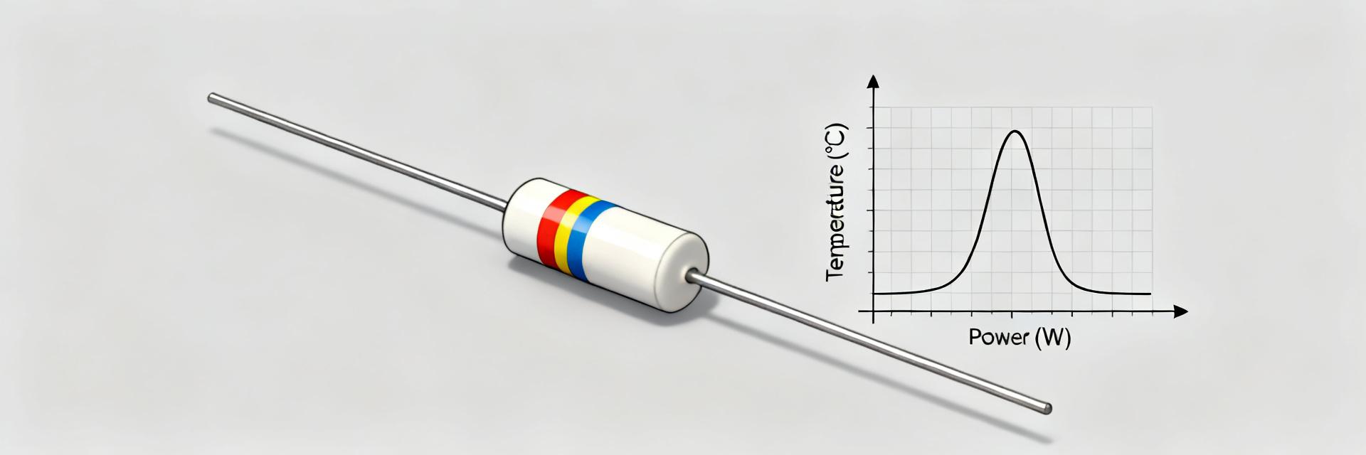
Power derating curve & thermal management
Datasheets usually specify a derating curve: full rated power up to a defined ambient, then linear derate to zero at maximum temperature. If a datasheet shows derating from 70 °C to 155 °C, a part at 60 °C ambient is at full 1 W. However, PCB mounting raises part temperature; for example, if board and local heating produce a 30 °C rise so the resistor sees 90 °C, derated power ≈ 1 W × (1 − (90−70)/(155−70)) ≈ 0.765 W. Engineers must convert ambient+self‑heating to part temperature before applying the curve.
Pulse/overload limits, surge withstand and safety features
Pulse and overload specs in the datasheet typically state pulse power, duration and duty cycle; convert these to allowable transient voltage with V_peak = sqrt(P_pulse·R). For example, a 10 W, short pulse across 680 Ω yields V_peak ≈ sqrt(10·680) ≈ 82.5 V. Flameproof or safety test notes indicate whether catastrophic failure is contained; always verify test conditions and sample sizes before assuming field reliability.
How to verify and test electrical specs in the lab (method guide)
Recommended measurement setups and tolerances
Use 4‑wire resistance measurement for sub‑ohm accuracy, otherwise 2‑wire with lead compensation is acceptable at hundreds of ohms. Stabilize temperature (thermal chamber or long soak) before reading. Test procedure: (1) record ambient and fixture temp, (2) measure cold resistance after 10‑minute stabilization, (3) apply rated steady dissipation and recheck after thermal steady state (typical settle 3–5 minutes), (4) compare to ±15% tolerance and include TCR allowance for elevated temps.
Replicating datasheet tests (pulse, overload, temperature)
To reproduce pulse tests, use a pulse current source or generator with controlled duty and duration, a current probe or shunt for accurate measurement, and a thermocouple on the resistor body. Document pulse width, repetition rate, measured peak voltage/current, and part temperature. Safety checklist: proper fusing, remote monitoring, protective shielding and conservative sample counts to map to datasheet claims.
Selection, substitution and application checklist (actionable guidance)
Selection criteria & acceptable substitutions
Decision points: required continuous power, expected transients, tolerance, TCR, operating temperature extremes, flameproof/safety class, physical size and mounting style. Rules of thumb: increase power rating by 2× under poor airflow or high board temperature; choose lower TCR if drift exceeds circuit margin; prefer explicit pulse ratings when transients are present.
PCB mounting, soldering and reliability tips
Trim leads to keep a small standoff for cooling, use solder profiles compatible with axial parts, and allow spacing for heat dispersion. Expect the primary lifetime stressors to be thermal cycling and high‑energy transients; include fusing or snubbers if transient energy approaches datasheet pulse limits. Designer checklist (copyable):
- Confirm derating curve and compute part temperature under worst case.
- Validate pulse withstand vs expected transients (convert to V/I).
- Allow tolerance + TCR in worst‑case resistance budgets.
- Check flameproof/safety notes where required.
- Ensure PCB spacing and standoff for cooling.
- Use appropriate solder profile for axial parts.
- Run sample lab verification with 4‑wire and thermal logging.
- Derate power by 2× if airflow is poor.
- Include fusing/snubbing if transient energy uncertain.
- Document test conditions and lot traceability for production.
Summary
- The ROX1SJ680R datasheet lists a 680 Ω, ±15% metal‑oxide resistor rated 1 W with typical TCR ≈ ±350 ppm/°C and operating range −55 °C to +155 °C; these numbers drive selection, derating and lab verification steps for reliable designs.
- Always convert datasheet pulse specs to V/I using V = √(P·R) and compute part temperature from ambient plus self‑heating before applying derating curves; conservative margins reduce field failures.
- Replicate key datasheet tests in a controlled lab (4‑wire resistance, pulse generators, thermal probes), document conditions and include the ten‑item checklist before release to production.
Frequently Asked Questions
What steady current will the ROX1SJ680R allow at 1 W?
Using P=I²R, the steady current that produces 1 W across 680 Ω is I = sqrt(1/680) ≈ 38.4 mA. Designers should reduce this for elevated part temperature or limited airflow because derating reduces continuous power capability; always recompute using actual part temperature.
How much resistance change does the ROX1SJ680R show over temperature?
With TCR ≈ ±350 ppm/°C (0.035%/°C), a 100 °C increase shifts resistance by ≈3.5%. For example, 680 Ω at 25 °C becomes ≈704 Ω at 125 °C. Include this drift plus ±15% tolerance when budgeting circuit margins.
How should an engineer test pulse withstand for the ROX1SJ680R?
Use a pulse generator with controlled duration and duty cycle, measure peak current/voltage and mount a thermocouple on the body. Convert allowed pulse power to voltage with V_peak = sqrt(P_pulse·680). Document pulse width, repetition, measured temperatures and compare to datasheet test conditions.
What is the typical application and mounting style for ROX1SJ680R?
The ROX1SJ680R features an axial leaded package designed for through-hole PCB mounting. Common applications include snubber circuits, precharge networks, bleeder resistors, and general-purpose power dissipation in industrial environments.