5W Metal-Oxide 47K Resistor: Spec Checklist & Limits
Distributor inventories and datasheet surveys show many similar SKUs with differing max working voltages, derating curves, and case sizes that cause mis-selection and field failures. This spec checklist guides engineers and technicians through measurable specs, safe operating limits, test procedures, and a selection checklist for reliable use of a 5W metal-oxide 47K resistor in power and signal circuits.
1 — Background: what a 5W metal-oxide 47K resistor is and where it’s used
Construction & materials
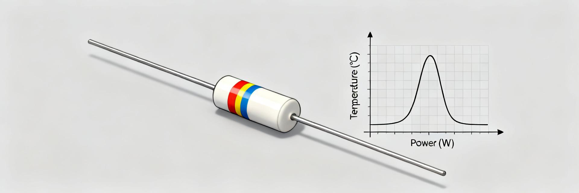
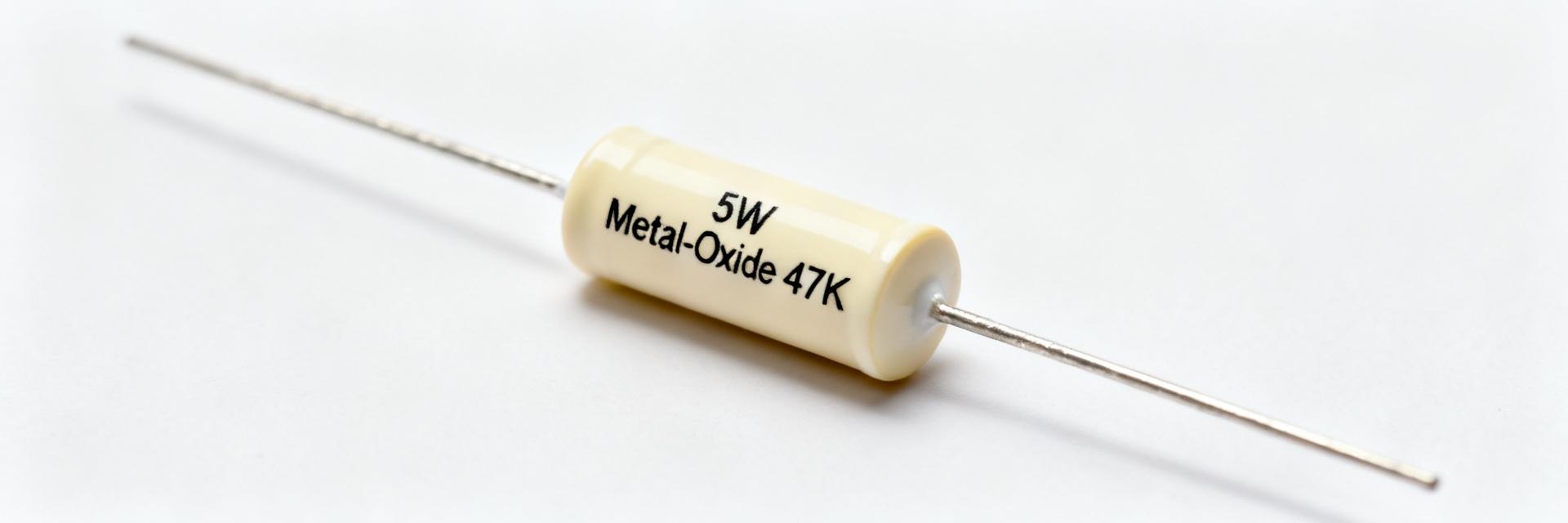
Metal-oxide film resistors use a deposited metal-acid oxide layer on a high-grade ceramic core, typically encapsulated in a flameproof cement body for power ratings. Compared with carbon or metal film, metal-oxide structures deliver superior temperature stability and high-surge tolerance, though at a larger physical volume. The flameproof cement coating improves safety in fault conditions but increases thermal mass, demanding strict PCB thermal relief and spacing.
Typical applications & form factors
Common uses include power-supply bleed/discharge networks, high-voltage snubbers, inrush current damping, and specialized audio terminal stages where high stability under power is needed. These components are predominantly axial-leaded ceramic/cement bricks or radial-leaded power shapes. Their physical dimensions exceed standard thin-film resistors, requiring broad lead-spacing designs to allow convective airflow and prevent heat transfer to adjacent elements.
2 — Spec checklist: what to verify on the datasheet
Mandatory electrical specs to read
Never rely solely on nominal values. When reviewing product datasheets, carefully extract the electrical boundaries listed in the table below to verify compatibility with circuit load points.
| Parameter Type | Specific Metric | Engineering Importance |
|---|---|---|
| Electrical | Resistance Tolerance (e.g., ±1%, ±5%) | Determines accuracy in bleeder time constants and power balance. |
| Electrical | Maximum Working Voltage (V_RMS) | Absolute dielectric voltage limit, regardless of calculated power. |
| Electrical | Temperature Coefficient (TCR) | Defines resistance drift over high operating temperature changes. |
| Thermal | Derating Transition Temp (T_Derate) | The ambient temperature above which maximum wattage degrades. |
| Safety | Overload Resistance / Overvoltage limit | Defines tolerance to short-duration transient voltage surges. |
Mechanical, thermal & compliance specs
Verify physical body dimensions, terminal lead thickness, and recommended mounting footprint layouts. Calculate the thermal resistance if ambient air cooling is restricted. Review flame-retardant standard compliance (e.g., UL 94V-0) and environmental compliance standards, including RoHS and REACH, to align with regulatory supply chains.
3 — Electrical limits and quick calculations for 5W metal-oxide 47K resistor
Continuous voltage and current limits (worked example)
Using the power relation formula \(P = \frac{V^2}{R}\), we compute the theoretical thermal voltage boundary for a 5W, 47,000 Ω resistor:
$$\text{Theoretical } V_{\text{max}} = \sqrt{P \times R} = \sqrt{5\,\text{W} \times 47,000\,\Omega} \approx 484.77\,\text{V}$$
The maximum theoretical continuous current is derived as:
$$I_{\text{max}} = \frac{V_{\text{max}}}{R} = \frac{484.77\,\text{V}}{47,000\,\Omega} \approx 10.31\,\text{mA}$$
Warning: This continuous voltage limit is strictly thermal. Real-world component datasheets often set a maximum dielectric working voltage (e.g., 350V or 500V) lower than the thermal capacity. Design around the lower of these two constraints.
Overload, surge and voltage-coefficient considerations
Metal-oxide structures accommodate short-duration surges better than metal films. However, repeated sub-millisecond pulses induce mechanical expansion stresses, causing progressive internal fractures. Additionally, high electric field gradients reduce the local resistance value—a parameter known as the Voltage Coefficient of Resistance (VCR). Realize your peak pulse safety envelope based on manufacturer surge curves.
4 — Thermal behavior, derating and mounting best practices
Derating rules and calculation example
Typically, power ratings are valid up to an ambient temperature of 70°C, above which performance degrades linearly to zero at 155°C or 200°C. For a 5W resistor rated for full power up to 70°C, derating to 0W at 155°C, the derating slope is:
$$\text{Slope} = \frac{-5\,\text{W}}{155^\circ\text{C} - 70^\circ\text{C}} \approx -0.0588\,\text{W}/^\circ\text{C}$$
At an elevated industrial enclosure temperature of 100°C, the safe continuous wattage ceiling drops to:
$$P_{\text{safe}} = 5\,\text{W} - (30^\circ\text{C} \times 0.0588\,\text{W}/^\circ\text{C}) \approx 3.24\,\text{W}$$
Mounting, airflow and PCB layout tips
- Maintain a minimum of 3mm to 5mm vertical clearance off the circuit board to allow convective air circulation.
- Do not place heat-sensitive semiconductors, electrolytics, or optocouplers directly adjacent to the power resistor.
- Utilize wide thermal-relief copper pads around lead connections to disperse conducted heat throughout the PCB layers.
5 — Measurement & test procedures to validate real-world behavior
Safe bench tests for power handling
When running evaluations, utilize a current-limited high-voltage DC source. Incrementally increase the voltage to bring the resistor up to its expected operating wattage. Allow several minutes at each power level to achieve thermal equilibrium, recording the surface temperature using a K-type thermocouple attached directly to the body or an un-reflective IR imaging camera.
Diagnostic checks & interpreting results
Measure the nominal cold resistance before and after thermal evaluations. A permanent change in cold resistance exceeding ±1% indicates internal structural degradation due to excessive core temperature. Visually inspect the cement encapsulation for hairline fractures, localized color browning, or flaking, which indicate hot-spot stress.
6 — Failure modes, a short case study and remediation steps
Common failure scenarios
- Dielectric Breakdown: Continuous voltage exceeded the physical insulation maximum, creating a carbonized conductive channel on the core.
- Cumulative Pulse Fatigue: Repetitive transients without safe interval cool-down caused progressive structural microfractures, culminating in an open circuit.
- Thermal Overrun: Confined enclosure spaces allowed heat to build up beyond the safe derating limit, leading to catastrophic outgassing.
How to fix, test and prevent recurrence
If field failures point to overstress, transition the bill of materials to a higher-rated 7W or 10W variant, or connect two 23.5kΩ, 2.5W units in series to halve localized dielectric voltage strain. Complement the design with transient clamping devices like Metal Oxide Varistors (MOVs) or TVS diodes directly across the power input lines.
7 — Selection & sourcing checklist for production and repairs
What to specify on BOM and purchase orders
Ensure that procurement documents define complete technical specifications. Avoid using generic terms; instead, write explicit descriptions, for example: Resistor, Metal Oxide, 47k Ohm, 5W, ±5%, Axial, Flameproof Cement, Min 500V Working Voltage. Always list approved manufacturing brands to prevent substitution with lower-grade components.
Installation & maintenance checklist
Prior to mass production, verify that lead-bending tools do not stress or compromise the ceramic-to-lead seal. Implement regular maintenance routines to inspect high-power circuits, checking for board discoloration, checking connection joints for thermal cycling fatigue, and verifying that cooling vents remain unblocked.
Summary
- Verify limits: Cross-reference calculated thermal voltages with physical working voltage parameters on the datasheet.
- Apply derating: Reduce the maximum operating wattage based on the actual ambient environment temperatures.
- Ensure proper airflow: Elevate axial parts off the PCB and optimize component placement to manage heat.