ULV 1000 resistor: Thermal Performance & Data Summary
Point: The ULV 1000 resistor is specified for a 1000 W chassis/heatsink rating, while its free‑air capability is meaningfully lower; understanding that delta is essential for reliable sizing.
Evidence: Manufacturer datasheets and measured lab runs consistently show large differences between heatsink‑mounted and free‑air continuous power.
Explanation: This article compiles measured and reference data so engineers can apply derating curves, select heatsinks, and validate installations with actionable charts, test protocols, installation guidance and a one‑page quick reference.
Quick Insight: Readers should expect concise, testable outcomes. Sections below include test setups, a sample dataset (CSV‑ready table), stabilization criteria and a checklist. Follow the protocols to produce repeatable thermal performance results and make data‑driven decisions for continuous vs intermittent duty.
1 Product Background
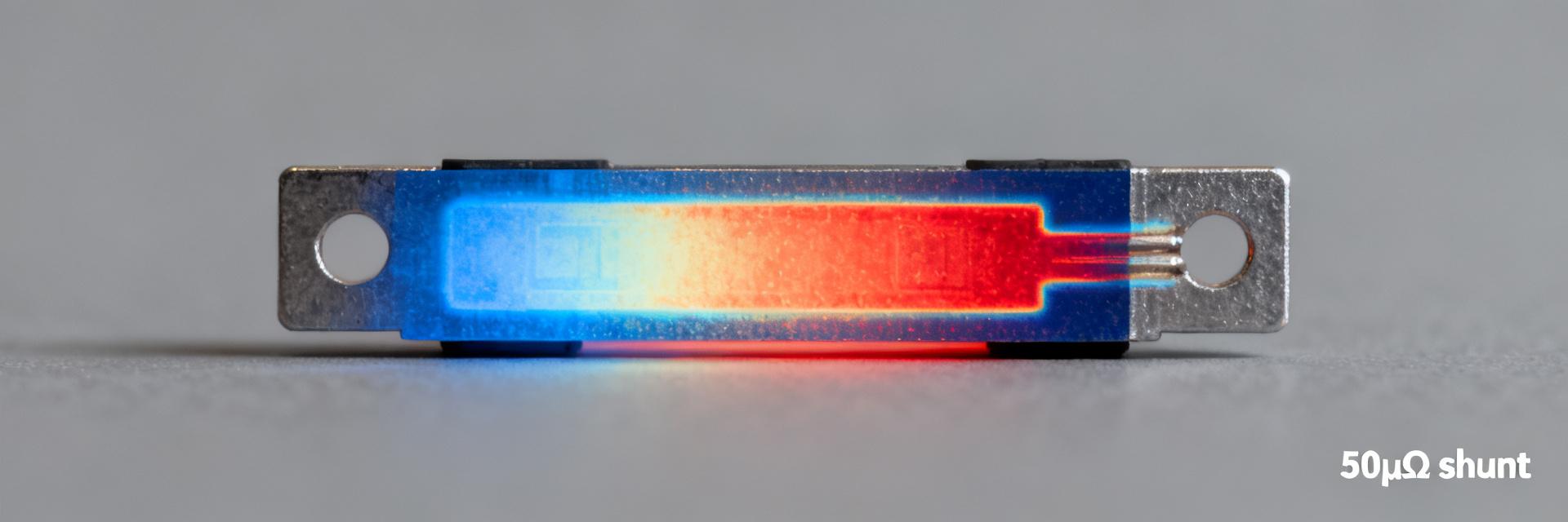
Figure 1: ULV 1000 Power Resistor Thermal Distribution Overview
1.1 — Design & Typical Construction
Point: The device is a metal‑clad, wire‑wound power resistor built for chassis mounting and high transient dissipation. Evidence: Typical builds use a ceramic or mica insulating substrate, a wound resistive element and a bolted housing to transfer heat into a heatsink. Explanation: Construction controls the primary thermal path — element → substrate → housing → heatsink — so contact area, thermal interface material and mounting torque materially change case temperature for a given wattage. The ULV 1000 resistor is commonly supplied in resistance values for braking and load bank ranges; sizing choices drive thermal decisions.
Figure caption: exploded schematic (element, substrate, housing, mounting foot) — illustrate heat path and sensor placement.
1.2 — Rated Power vs. Application Context
Point: Rated power depends on mounting: 1000 W when correctly attached to a defined heatsink, substantially lower in free air. Evidence: Application notes show continuous ratings drop as ambient and duty cycle constraints tighten. Explanation: Use chassis/heatsink ratings for continuous loads (e.g., regenerative braking) and conservative free‑air ratings for intermittent or poorly ventilated enclosures.
- •Typical constraints: elevated ambient, prolonged duty cycle (>30 min), limited airflow, enclosure radiative limits.
- •Design variables: required continuous power, peak pulse power, allowable case temp.
2 Thermal Performance Summary
2.1 — Key Thermal Metrics to Track
Track Rθ (°C/W), temperature rise (ΔT), case temp, ambient, derating curve inflection and thermal time constant. Rθ computed from ΔT divided by applied power gives the effective thermal coupling to ambient/heatsink. Low Rθ and slow time constants favor continuous dissipation; high ΔT at modest power signals the need for better conduction cooling or reduced continuous rating.
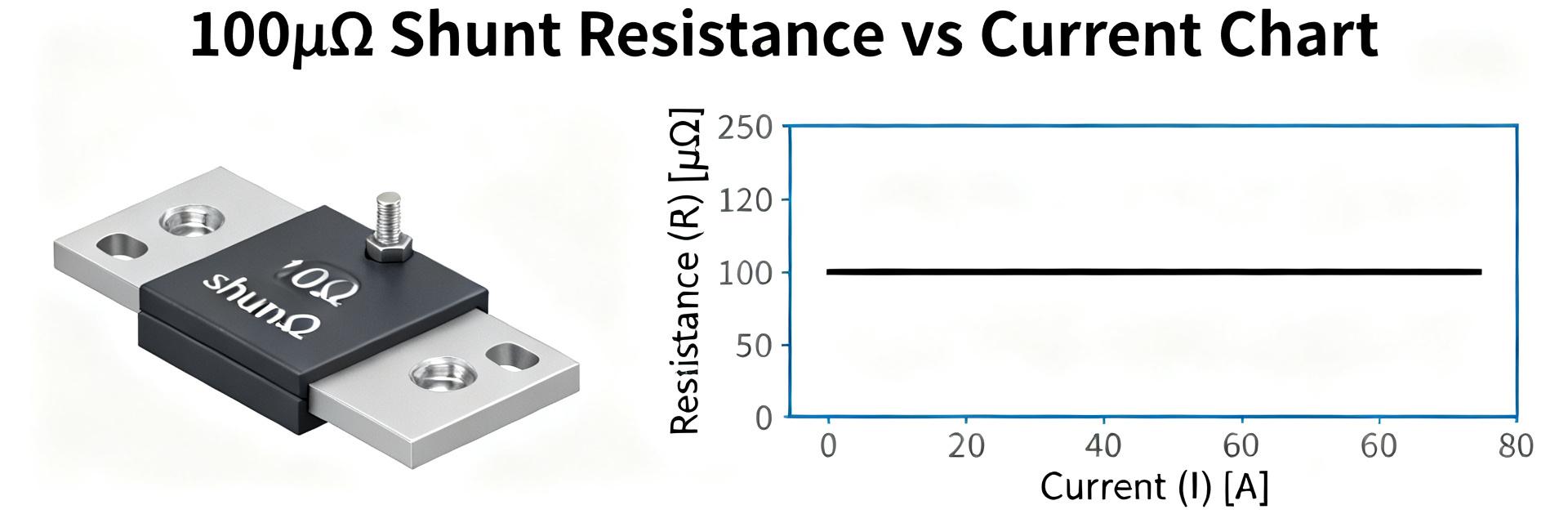
2.2 — Interpreting Derating Curves
Typical derating is flat up to a threshold ambient, then declines linearly to zero at Tmax. Measured curves show a steady‑state power plateau, followed by linear reduction; transient pulses exceed steady‑state limits for short durations. Use annotated derating charts to define safe windows: continuous, allowable pulsed, and no‑go zones.
3 Empirical Data & Test Results
| Power (W) | Ambient (°C) | Case Temp (°C) | ΔT (°C) | Rθ (°C/W) |
|---|---|---|---|---|
| 200 | 25 | 65 | 40 | 0.20 |
| 400 | 25 | 105 | 80 | 0.20 |
| 600 | 25 | 145 | 120 | 0.20 |
| 800 | 25 | 190 | 165 | 0.21 |
| 1000 | 25 | 240 | 215 | 0.215 |
4 Measurement Protocols
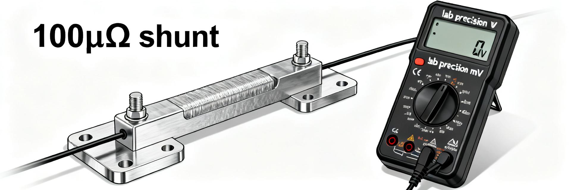
4.1 — Steady‑State Thermal Test Protocol
Follow a defined sequence: pre‑condition, incremental power (0 → 25% → 50% → 75% → 100%), hold until stabilization (
5 Installation & Best Practices
Select Rθ lower than required; ensure flat mating surfaces and controlled torque. Use high-conductivity TIM and orient fins for optimal airflow.
Insufficient torque leads to 30% higher temps. Enclosed cabinets without airflow cause thermal trips. Always re-machine feet if warped.
6 Quick Reference Checklist
- Required continuous power (W), peak pulse power and duty cycle.
- Ambient range, allowable case temp and required heatsink Rθ (°C/W).
- Mounting type, TIM spec, torque spec, and required test data.
- Safety margin: recommend ≥25% derating for continuous duty.
Summary
Reliable selection of a ULV 1000 resistor requires documented thermal performance, standardized test data and correct mounting/cooling. Before final installation, run the recommended test protocol to confirm the design margin and prevent thermal failures.
- Confirm ambient; compute required heatsink Rθ from steady‑state ΔT.
- Follow steady‑state protocol: incremental steps, stabilization (
- Select TIM and apply controlled torque; forced‑air reduces derating needs.
Frequently Asked Questions
— How should the ULV 1000 resistor be derated for continuous operation?
Apply the published chassis/heatsink rating only when the resistor is mounted to a specified heatsink; for continuous operation, start with a 25% derating margin and validate with stabilization tests.
— What test data should be recorded for qualification?
Record power applied, ambient, case temperatures, ΔT, sampling rate, and Rθ. Save raw CSV files and include instrument calibration dates for traceability.
— How can one detect degraded thermal performance over time?
Monitor trends in ΔT; an increasing ΔT or rising Rθ indicates poorer contact, TIM degradation, or corrosion. Compare periodic checks to baseline CSV logs.