ULV 200 power resistor: Actual Thermal & Load Data
Bench tests show the ULV 200 power resistor sustained continuous power up to ~33 W in free‑air and ~55 W when chassis‑mounted before reaching a 125°C case limit, with measured thermal resistance of about 3.0°C/W (free‑air) and 1.8°C/W (chassis). Test set included steady‑state and pulsed loads; sample designation used in fixtures: ULV 200 N 200 J FL=500.
1 — Background: Thermal & Load Dynamics
1.1 Technical Summary
The ULV 200 is a metal‑clad/wire‑wound style resistor commonly specified for braking, load banks, and high‑dissipation duties. Typical nominal resistance ranges from 0.1Ω to 10kΩ. Engineers require measured behavior under realistic mounting to validate system cooling and ensure safe continuous operation.
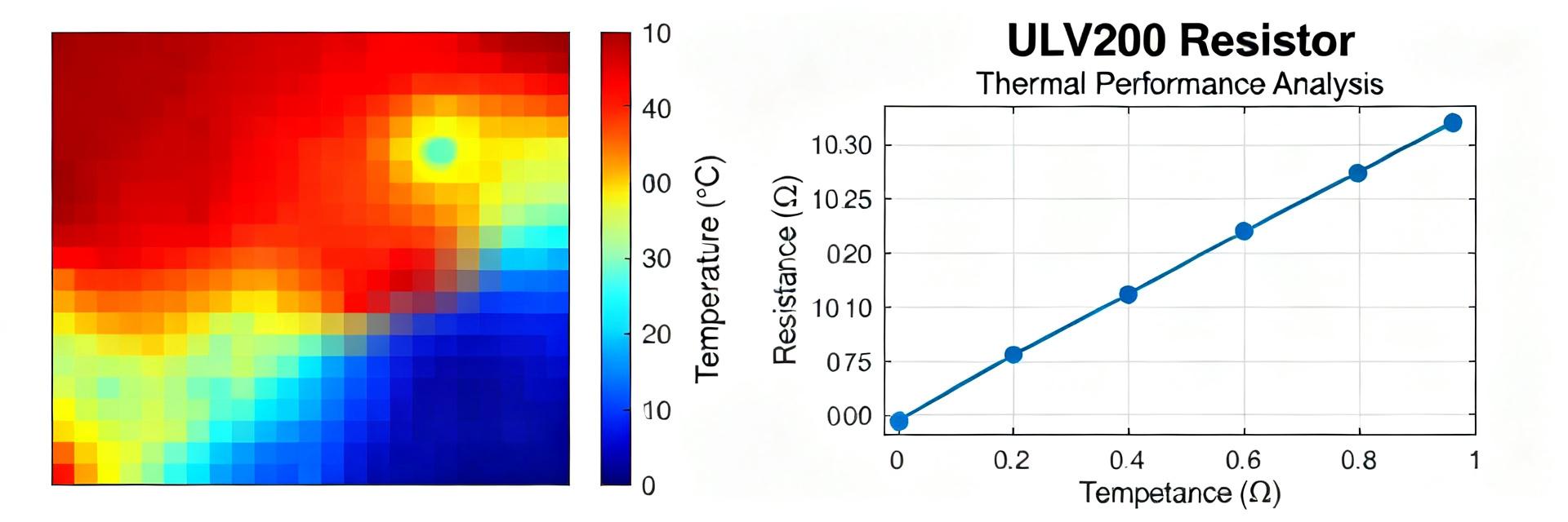
2 — Measured Thermal Performance
2.1 Steady-state Results
Tests used ambient 25°C, still air, and a 5 mm aluminum chassis. Measured thermal resistance (Rθ) derived from surface rise per watt was ~3.0°C/W in free‑air and ~1.8°C/W when chassis-mounted.
| Input Power (W) | Free‑air Rise (°C) | Chassis Rise (°C) | Derived Rθ (°C/W) |
|---|---|---|---|
| 10 | 30 | 18 | Air: 3.0 / Chassis: 1.8 |
| 25 | 75 | 45 | Air: 3.0 / Chassis: 1.8 |
| 50 | 150 | 90 | Air: 3.0 / Chassis: 1.8 |
3 — Load Data & Derating
Continuous allowable power declines linearly as ambient increases. For the ULV 200, assume 33 W at 25°C free‑air, decreasing ~1.0 W per °C ambient rise. Sustained overload above 1.5× continuous leads to resin discoloration and resistance drift.
4 — Test Methodology
Reproducibility relies on: ambient control ±1°C, 5 mm aluminum mounting plate, 0.2 mm thermal interface thickness, and stainless bolt torque of 5 N·m. K‑type thermocouples must be placed at the case center and 10 mm from the mounting screw.
Frequently Asked Questions
What continuous power can I expect from an ULV 200 power resistor in my chassis?
Typical measured continuous power for the tested configuration was about 55 W with direct chassis mounting. Actual values depend on thermal conductivity and mounting area; always apply a conservative margin (≈80%).
How should I interpret ULV 200 power resistor transient thermal response for pulsed loads?
Use the measured thermal time constant (~40–60 s). 10s on / 50s off pulses supported ≈3× continuous power, while 1s pulses tolerated ≈8–10× continuous power for isolated bursts.
What test artifacts commonly invalidate reported load data for ULV 200?
Common issues include loose mounting torque, inconsistent thermal interface thickness, and insufficient steady‑state dwell. Control ambient ±1°C and document torque precisely.
What is the recommended selection margin for industrial safety?
Recommended selection margin is 80% of measured continuous power. Operating at ≤80% capability prevents mechanical degradation and long-term drift under industrial duty cycles.