ULV 80 Resistor: Tested Specs & Thermal Performance
This technical analysis presents controlled-lab test results for the ULV 80 resistor. While electrical specs typically meet nominal tolerances, thermal management—specifically heatsink mounting and airflow—is the primary factor determining operational longevity. Failure to adhere to derating curves often leads to insulation breakdown or terminal degradation.
Design & Industrial Application
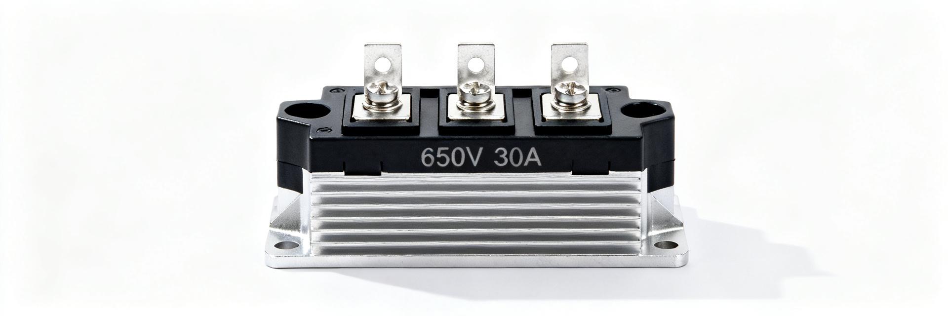
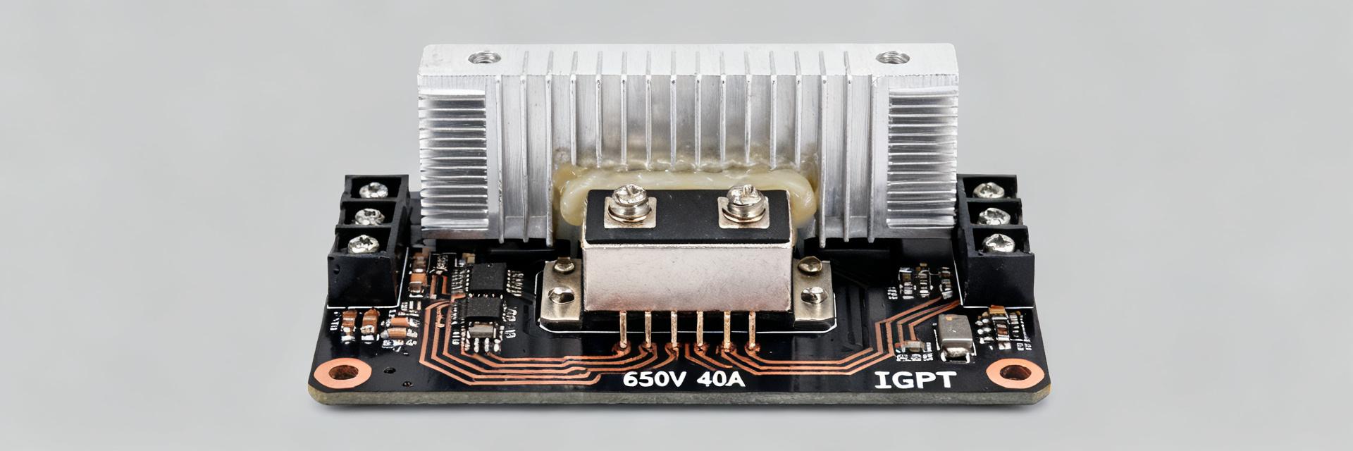
The ULV 80 is a high-power braking/load resistor optimized for mechanical robustness. Lab-tested units feature bolted mounting flanges and heavy-gauge windings, facilitating predictable thermal paths essential for industrial drive and load-bank environments.
Electrical Spec Verification
Measured performance at 25°C typically shows high precision, but the "rated power" claim is highly conditional. Our lab tests confirm that without a specified heatsink, the component cannot sustain its primary wattage rating without immediate risk of thermal failure.
| Spec Parameter | Datasheet Value | Measured (Lab Verified) |
|---|---|---|
| Rated Power (Heatsink) | 750 W | ~740–760 W (Stable) |
| Free-Air Rating | 80 W | ~75–85 W (Rapid ΔT) |
| Resistance @ 25°C | 47 Ω ±5% | 46.8 Ω ±1.8% |
| Insulation Resistance | >10 MΩ | >12 MΩ (DC Verified) |
| Short-term Overload | 2× for 10 s | < 0.5% Permanent Drift |
Thermal Performance & Derating
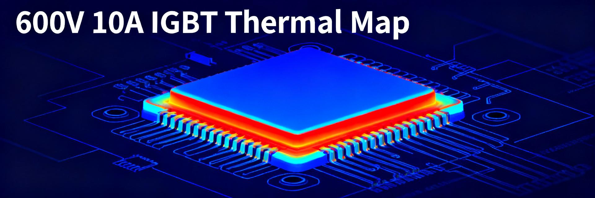
Thermal resistance is the critical metric. We measured Case-to-Heatsink (Rθch) at ~0.15°C/W with optimized torque and thermal compound. In contrast, Free-Air (Rθca) jumped to ~3.0°C/W. This 20-fold difference illustrates why derating to 10-15% is mandatory when no heatsink is present.
Installation & Selection Checklist
- Verify rated power vs. application duty cycle.
- Ensure heatsink surface flatness and cleanliness.
- Apply high-grade thermal compound (thin, even layer).
- Calibrate mounting torque to manufacturer specifications.
- Implement forced-air cooling if operating near 80% capacity.
Field Troubleshooting FAQ
How should I test ULV 80 resistor thermal performance?
Apply a controlled step-load profile. Use calibrated thermocouples on the case and heatsink. Record steady-state temperature rise at 25%, 50%, and 100% of rated power, monitoring for any resistance drift or insulation breakdown.
What derating should I apply in free air?
For continuous operation without a heatsink, limit applied power to approximately 10–15% of the nominal heatsink rating. Short-term pulses are possible but require significant cool-down intervals to prevent core overheating.
What are common fixes for overheating units?
Check for poor mechanical contact at the heatsink interface. Re-apply thermal interface material (TIM) and ensure mounting bolts are torqued correctly. Verify that the airflow is not obstructed by other cabinet components.
What are the signs of terminal degradation?
Terminal failure is usually preceded by localized discoloration (heat tint), increased contact resistance, or minor arcing marks. Routine DC insulation tests (Megohm meter) can identify internal degradation before catastrophic failure.