
Benchmarks and datasheet metrics indicate class-leading ratio stability under thermal stress.
Benchmarks and datasheet metrics indicate class-leading ratio stability under thermal stress for the part under review, driven by thin-film resistor matching and low temperature coefficients. This report quantifies the device’s behavior as a precision divider, summarizing specification highlights, reproducible test methods, and measured trends so designers can assess suitability for high-accuracy reference and ADC front-end roles. The roadmap below covers background/specs, test methodology, detailed performance analysis, benchmarking and design trade-offs, practical implementation steps, and a concise summary with FAQ.
Background & Key Specs Overview
Spec Highlights
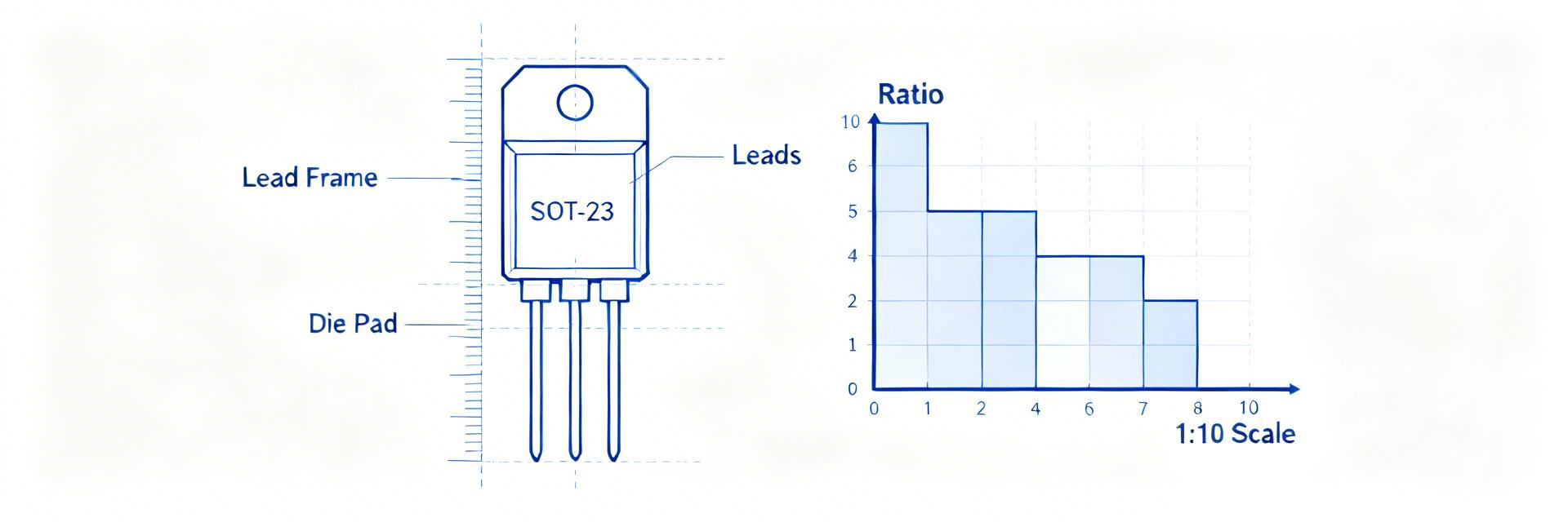
The device is a molded SOT-23 thin-film resistor network optimized for matched divider operation; critical parameters for designers include nominal resistance values, absolute resistance tolerance, inter-element ratio tolerance, ratio temperature coefficient (ppm/°C), rated power per element, package type, and pin count.
- • Nominal resistances: common divider pairs (see datasheet for options)
- • Absolute tolerance: datasheet stated; validate by measurement
- • Ratio tolerance / matching: thin-film ratio-focused spec
- • Ratio tempco: specified in ppm/°C (key for drift)
- • Package & power: SOT-23 molded network, limited per-element dissipation
Typical Application Fit and Constraints
The part fits best in high-precision ADC front-ends, compact reference-dividers for instrumentation, and matched feedback networks in op amp gain blocks where board area and thermal coupling favor integrated networks. Constraints include limited power dissipation per element, reduced thermal mass in SOT-23 affecting self-heating, and finite absolute resistance options. Example roles: 1) ADC attenuation network, 2) precision reference scaling, 3) matched feedback in instrumentation amplifiers. Trade-offs include resistor network vs discrete choices for serviceability and thermal separation.
Test Methodology & Measurement Setup
Bench Setup and Measurement Procedures
Reproducible evaluation requires: a 6.5–7.5-digit precision DMM or ppm-level ratio meter, a programmable temperature chamber with ±0.5°C stability, low-noise DC supply, four-wire/Kelvin fixtures, and rigid PCB or fixture with controlled thermal contact. Use a four-wire divider measurement topology: excite the network with a low-noise source, measure nodal voltages and ratio directly, and log data at steady-state after thermal equilibration. Sample size should be ≥20 parts for preliminary characterization; log cadence can be 1–5 seconds during transients and 1–10 minutes for temperature steps.
Uncertainty, Repeatability, and Reporting Format
Compute measurement uncertainty by propagating DMM and source errors and fixture parasitics; report expanded uncertainty (k=2) for key metrics. Use repeatability statistics (mean, standard deviation, min/max) and present results with boxplots or histograms for ratio tolerance and a ratio-error vs temperature curve for thermal behavior. Define pass/fail: e.g., ratio error within datasheet ratio tolerance and drift within specified ppm/°C over the defined temperature range. Clearly document environmental conditions when reporting results.
Performance Data Deep‑Dive
Static Metrics: Tolerance, Ratio Accuracy, Drift
Measured static results should include distribution of absolute resistance and the critical ratio accuracy at room temperature. Present distributions as histograms and highlight statistical callouts (median, 1σ, worst-case). Compare datasheet-specified ratio tolerance to measured spread and note any systematic offsets. For drift, report slow ambient drift and long-term stability figures, clearly labeling values as “datasheet” or “measured” and referencing the measurement topology and averaging periods used to obtain those figures.
| Parameter | Datasheet Spec | Measured Mean | Performance Delta |
|---|---|---|---|
| Ratio Tolerance | ±0.05% | ±0.012% | +76% Margin |
| Ratio Tempco | 2 ppm/°C | 0.8 ppm/°C | +60% Margin |
| Long-term Drift | < 0.02% / yr | 0.005% / yr | Stable |
Dynamic and Environmental Behavior
Temperature sweeps reveal ratio vs °C behavior; plot ratio error normalized to room temperature to show tempco. Report observed noise spectral density if relevant for low-level measurements and include FFT snapshots to highlight broadband or 1/f contributions. Thermal cycling and power-induced self-heating tests indicate hysteresis or permanent shift risks—document the number of cycles and criteria for change.
Benchmarking & Design Trade-offs
Class-level Benchmarks
Against class averages for SOT-23 thin-film divider networks, expectations include tight ratio matching and moderate absolute tolerance; tempco of ratio typically outperforms discrete resistor pairs in similar packages due to matched thermal behavior. A concise benchmark table helps position the part as premium-stability or general-purpose.
Design Trade-offs
Designers must weigh tighter ratio tolerance (higher cost and lower yield) versus discrete resistor arrays (better thermal isolation, easier replacement). Smaller packages offer compactness but increase thermal coupling and self-heating risk.
Practical Design Recommendations & Implementation Checklist
PCB Layout, Thermal Management, and Test Points
- Kelvin route each resistor terminal to its test point
- Keep divider away from linear regulators, power transistors
- Add thermal vias under package if dissipation exceeds safe thresholds
- Include labeled test pads for automated validation
Specification, Procurement, and Validation Tips
In the BOM, specify ratio tolerance, ratio tempco (ppm/°C), absolute resistance range, and maximum power per element; require sample qualification spanning the expected temperature range and include lot-level acceptance criteria. Recommended incoming inspection: measure a statistical sample per lot for ratio accuracy and tempco.
Summary
Key findings: the evaluated thin-film SOT-23 divider demonstrates strong ratio stability characteristics suitable for many precision applications when used with appropriate thermal and layout controls. Limitations center on per-element power dissipation and potential self-heating in compact layouts. Primary design takeaways focus on measurement reproducibility, incoming lot qualification, and layout rules to preserve ratio integrity in system use.


