What components and modules does a capacitor wiring diagram contain?
What Components and Modules Does a Capacitor Wiring Diagram Contain?

I. Introduction
Capacitors are fundamental components in electrical engineering, playing a crucial role in various circuits. A capacitor is a passive electronic component that stores electrical energy in an electric field, allowing it to release that energy when needed. Understanding how to read and interpret capacitor wiring diagrams is essential for engineers, technicians, and hobbyists alike. This article aims to explore the components and modules found in capacitor wiring diagrams, providing insights into their functions and applications.
II. Overview of Capacitors
A. Basic Function of Capacitors
Capacitors serve several key functions in electrical circuits. They can store energy, filter signals, smooth out voltage fluctuations, and even help in timing applications. When a voltage is applied across a capacitor, it accumulates charge, which can be released when the circuit requires it. This ability to store and release energy makes capacitors invaluable in various applications.
B. Types of Capacitors
There are several types of capacitors, each with unique characteristics and applications:
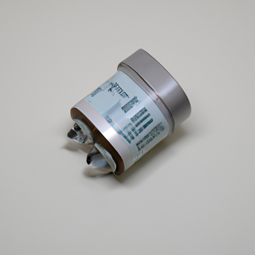
1. **Electrolytic Capacitors**: These capacitors are polarized and typically used in power supply circuits due to their high capacitance values. They are often found in applications requiring significant energy storage.
2. **Ceramic Capacitors**: Known for their stability and reliability, ceramic capacitors are commonly used in high-frequency applications. They are non-polarized and come in various capacitance values.
3. **Film Capacitors**: These capacitors use a thin plastic film as the dielectric material. They are known for their low loss and high stability, making them suitable for audio and RF applications.
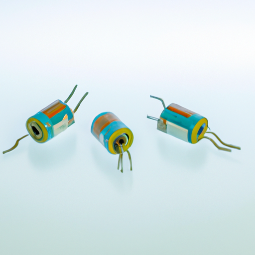
4. **Tantalum Capacitors**: Tantalum capacitors are also polarized and offer high capacitance in a small package. They are often used in compact electronic devices.
C. Applications of Capacitors in Circuits
Capacitors are used in a wide range of applications, including power supply filtering, signal coupling and decoupling, timing circuits, and energy storage in power electronics. Their versatility makes them essential in both consumer electronics and industrial applications.
III. Components of a Capacitor Wiring Diagram
A. Capacitor Symbols
In wiring diagrams, capacitors are represented by specific symbols. The standard symbol for a capacitor consists of two parallel lines, with one line often curved to indicate a polarized capacitor. Variations exist based on the type of capacitor, such as the inclusion of a "+" sign for electrolytic capacitors.
B. Power Source
A power source is a critical component in any circuit involving capacitors. It provides the voltage necessary to charge the capacitor. In wiring diagrams, power sources are typically represented by a battery symbol or a voltage source symbol, indicating the connection to the capacitor.
C. Resistors
Resistors are often included in capacitor circuits to control the charging and discharging rates of capacitors. They limit the current flowing into the capacitor, preventing damage and ensuring proper operation. In wiring diagrams, resistors are represented by a zigzag line.
D. Inductors
Inductors can work in conjunction with capacitors to form resonant circuits. They store energy in a magnetic field and can influence the behavior of the circuit, particularly in filtering and oscillation applications. Inductors are represented by a series of loops in wiring diagrams.
E. Switches
Switches are essential for controlling the flow of current in capacitor circuits. They allow users to connect or disconnect the capacitor from the circuit, enabling or disabling its function. In diagrams, switches are typically represented by a break in the line, indicating their open or closed state.
F. Load Components
Load components are the devices that consume the energy stored in the capacitor. Examples include motors, lights, and other electronic devices. In wiring diagrams, load components are represented by their respective symbols, indicating their connection to the capacitor.
IV. Modules in a Capacitor Wiring Diagram
A. Circuit Modules
Circuit modules are predefined sections of a circuit that perform specific functions. They can include combinations of capacitors, resistors, and other components to achieve desired outcomes. Common examples include power supply modules and signal processing modules.
B. Filter Circuits
Filter circuits utilize capacitors to remove unwanted frequencies from signals. They can be low-pass, high-pass, band-pass, or band-stop filters, depending on the application. Capacitors play a crucial role in determining the cutoff frequency of these filters.
C. Timing Circuits
Timing circuits rely on capacitors to create delays or timing intervals. By charging and discharging at specific rates, capacitors can control the timing of events in a circuit, such as in oscillators or timers.
D. Oscillator Circuits
Oscillator circuits generate periodic waveforms, and capacitors are integral to their operation. They help determine the frequency of oscillation by interacting with inductors and resistors, allowing for the creation of sine, square, or triangular waves.
V. Reading and Interpreting Capacitor Wiring Diagrams
A. Understanding the Layout of Diagrams
Capacitor wiring diagrams typically follow a standardized layout, with components arranged logically to illustrate their connections. Understanding this layout is crucial for interpreting the diagram accurately.
B. Identifying Components and Their Functions
When reading a wiring diagram, it is essential to identify each component and understand its function within the circuit. This knowledge helps in troubleshooting and designing circuits effectively.
C. Common Mistakes to Avoid When Reading Diagrams
Common mistakes include misinterpreting symbols, overlooking component values, and failing to recognize the orientation of polarized components. Careful attention to detail can help avoid these pitfalls.
VI. Practical Applications of Capacitor Wiring Diagrams
A. Real-World Examples of Capacitor Wiring Diagrams
Capacitor wiring diagrams are prevalent in various applications, from simple electronic devices to complex industrial systems. Examples include power supply circuits, audio equipment, and motor control systems.
B. Importance in Troubleshooting and Repair
Understanding capacitor wiring diagrams is vital for troubleshooting and repairing electronic devices. Technicians can quickly identify faulty components and determine the necessary steps for repair.
C. Role in Circuit Design and Development
For engineers and designers, capacitor wiring diagrams are essential tools in the development of new circuits. They provide a clear representation of how components interact, facilitating the design process.
VII. Conclusion
In conclusion, understanding the components and modules found in capacitor wiring diagrams is crucial for anyone involved in electrical engineering. These diagrams provide valuable insights into how capacitors function within circuits and their applications in various technologies. As capacitor technology continues to evolve, further study and exploration in this field will be essential for future innovations.
VIII. References
For those interested in delving deeper into the world of capacitors and wiring diagrams, the following resources are recommended:
- "The Art of Electronics" by Paul Horowitz and Winfield Hill
- "Electronics for Dummies" by Cathleen Shamieh
- Online courses on platforms like Coursera and edX focusing on electrical engineering fundamentals.
By exploring these resources, readers can enhance their understanding of capacitors and their critical role in modern electronics.