


Helping you save cost and time.

Provide reliable packaging for your goods.

Quick and reliable delivery to save time.

Excellent after-sales service.
New Product Launch
More +


Hot Selling Parts


Blog
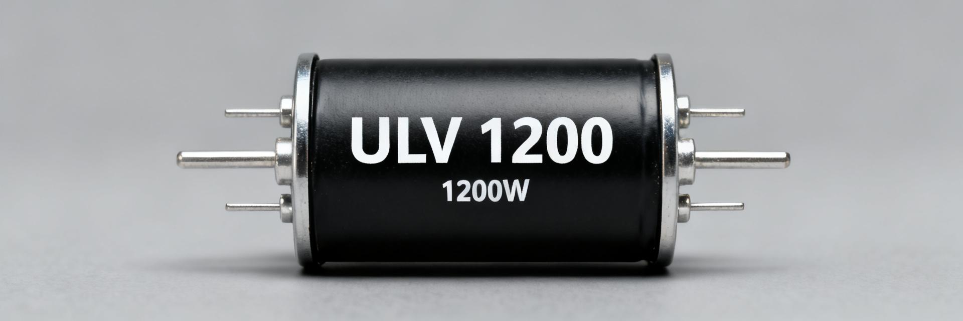
ULV 1200 Power Resistor Datasheet: Full Specs & Limits
The ULV 1200 is a 1200 W-class metal-clad, wire-wound power resistor engineered for heavy steady dissipation and demanding braking/load-bank duties. This technical guide breaks down the nominal 1200 W…
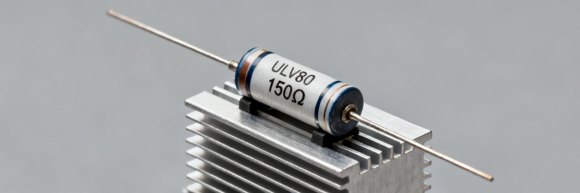
ULV80 Resistor 150Ω FL=1000: Complete Spec & Thermal Data
Thermal limits are the primary constraint for high-power metal-clad resistors: uncontrolled dissipation increases component temperature proportionally to power times thermal resistance, often causing …
ULV 80 Resistor: Tested Specs & Thermal Performance
2026-05-30 10:14:26
ULV 100 resistor Datasheet: Critical Specs & Charts
2026-05-28 10:15:25
ULV 500 Series Performance Report: Latest Thermal Specs
2026-05-27 10:14:23
ULV 1000 resistor: Thermal Performance & Data Summary
2026-05-23 10:05:26
ULV 200 N Datasheet Deep-Dive: Full Specs & Pulse Limits
2026-05-22 10:04:27
Read more