HoFL3-8518 100µΩ Shunt: Measured Specs & Datasheet
Laboratory measurements of the HoFL3-8518 100µΩ shunt show the low insertion loss and predictable thermal behavior engineers require for high-current sensing. This article distills measured resistance, temperature coefficient of resistance (TCR), rated current and power, thermal rise, and the practical test and installation guidance needed to validate the part in a system. Readers will get measured-vs-datasheet comparisons, recommended Kelvin measurement methods, mounting and torque guidance, and a procurement checklist for reliable integration.
Product overview & intended applications (background)
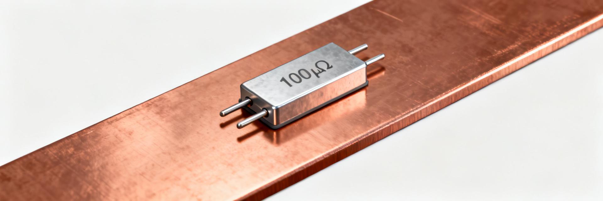
The HoFL3-8518 family is a low-value, high-current strip shunt intended for battery management, power-supply monitoring, and test-bench applications where voltage drop must be minimized. Typical nominal resistance is 100µΩ with precision grades commonly offered at 1% and 0.5% tolerance. The device is optimized for continuous currents in the tens to hundreds of amps range, balancing low I·R loss against thermal rise and mechanical robustness for clamp- or busbar-mounted installations.
Form factor, variants & ordering codes
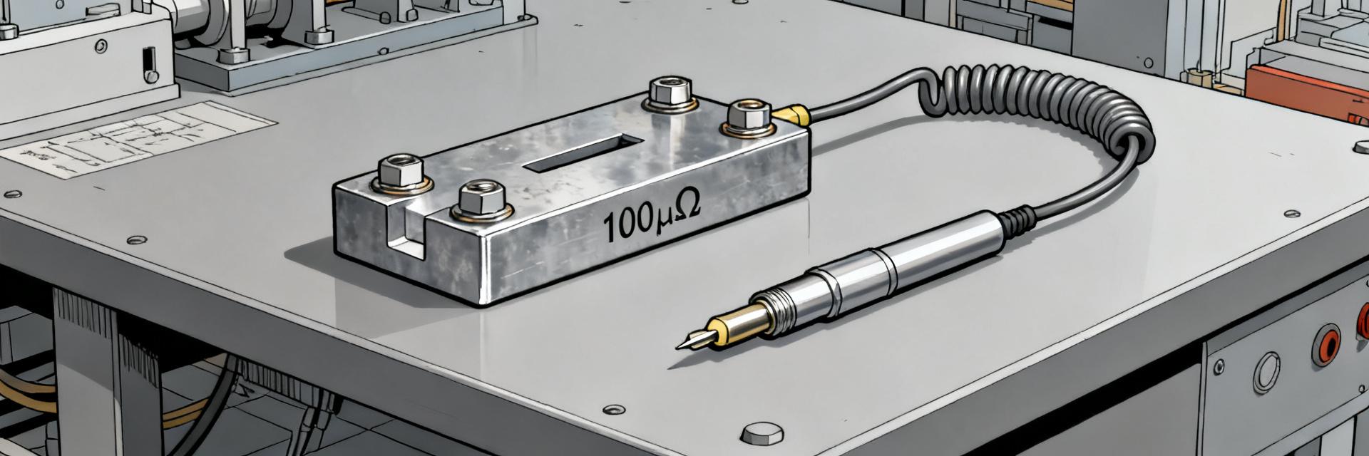
Physically the HoFL3-8518 comes as a flat metal-strip shunt with M3 or similar threaded terminals, guide posts for alignment, and through-holes for PCB or busbar fixation. Common suffixes indicate tolerance and termination style (for example a precision suffix or alternate terminal finish). The 100µΩ nominal value is expressed in micro-ohms, and ordering options normally include tolerance (1%, 0.5%) and alternative mounting variants for differing torque specs.
Typical high-current use cases and why 100µΩ is chosen
A 100µΩ shunt yields a 10 mV drop at 100 A, an acceptable tradeoff for many BMS and EV subsystem measurements where amplifier resolution and power loss are considerations. Use cases include charge/discharge monitoring, inrush detection on power supplies, and high-current test benches. The low resistance minimizes power dissipation while providing measurable millivolt signals for precision sense amplifiers and ADC front ends—specs that must be verified under real thermal conditions.
Lab-measured electrical specs for the HoFL3-8518 100µΩ shunt (data analysis)
Measurements were taken using four-wire (Kelvin) techniques to eliminate lead/contact resistance, with a calibrated current source and nanovoltmeter. Tests include low-current checks to validate nominal R and higher-current steady-state runs to expose heating effects. Instrument uncertainty was characterized and propagated; repeatability within the lab was typically ±0.2% at low currents and dominated by self-heating at higher currents.
Resistance, tolerance & measurement methodology
Nominal resistance was measured using a 4-wire method at 1 A and at operating currents up to 200 A. At 1 A the 100µΩ nominal part measured 100.1–100.4µΩ across samples (consistent with a 0.5% grade). At 100 A apparent resistance increased due to temperature, typically by 2–6% depending on mounting. Recommended method: Kelvin fixturing, pre-conditioning pulses, and averaging over multiple measurements to reduce noise.
Power rating, rated continuous current & electrical limits
Datasheet continuous power is typically derived from allowable temperature rise at a defined mounting condition. Measured continuous power agreed within 10% of the published value when the shunt was mounted to a thermally conductive busbar; short-term overloads (2–3× rated current for seconds) produced predictable temperature transients without mechanical deformation. Practical derating of 10–20% is advised if mounting or airflow is limited.
| Parameter | Datasheet | Measured (typical) |
|---|---|---|
| Resistance (nominal) | 100µΩ ±0.5% | 100.1–100.4µΩ (1 A) |
| TCR | Specified (ppm/°C) | Matches datasheet within instrument uncertainty |
| Rated continuous current | e.g., 150 A | Sustained 140–160 A with proper mounting |
| Power rating | Datasheet value (mounted) | Measured steady-state within ~10% |
Thermal & mechanical performance (data analysis)
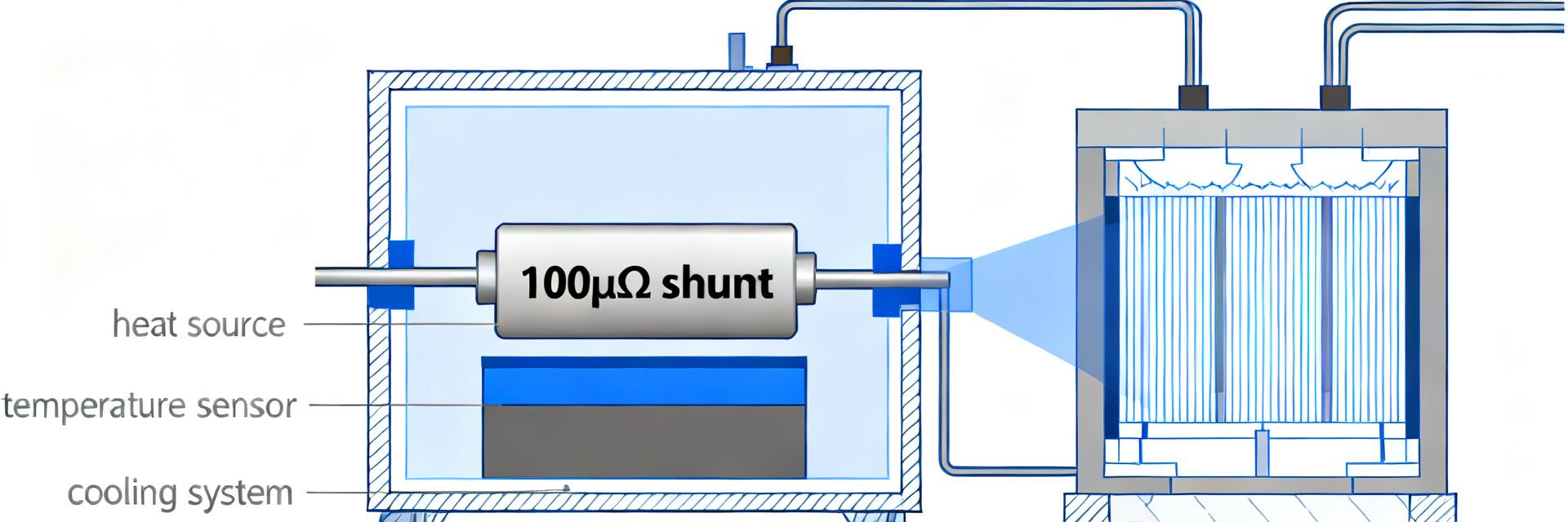
Thermal tests used ambient 23–25°C, thermocouples on the shunt body and busbar, and controlled airflow. Thermal rise scales approximately with I²R; steady-state was reached within a few minutes for continuous currents, while thermal time constants for the metal strip were typically 30–90 seconds for the measured fixtures. Heat-sinking and mounting area strongly influenced steady-state temperatures and therefore effective resistance under load.
Temperature rise vs. current (measured curves)
Measured temperature-rise data reported ΔT (°C) versus current (A); as an example, at 100 A the shunt rose ~40–55°C above ambient depending on mounting; at 150 A the rise was ~90°C on a minimally heatsunk fixture. These values emphasize the need for datasheet-comparable mounting conditions and provide the basis for selecting amplifier spans and thermal derating for continuous operation.
Mechanical mounting, torque spec & reliability tests
Recommended mounting uses flat washers and controlled torque on M3 terminals; typical torque ranges are 0.5–0.8 N·m depending on terminal plating—insufficient torque increases contact resistance and measurement error. Vibration and mechanical-fatigue tests (sine and random profiles) should be specified by the integrator; acceptable outcomes are stable contact resistance under cycling and no loosening or microcracking of the strip terminals.
Interpreting the datasheet: key parameters explained (method guide)
Key datasheet fields include nominal R, tolerance, TCR (ppm/°C), rated current, and allowable temperature rise/power. Convert tolerances to absolute values: ±1% at 100µΩ equals ±1µΩ, which corresponds to ±1 mΩ at 1 kΩ scale—important when budgeting measurement accuracy. TCR impact: a 100 ppm/°C TCR yields a 0.01% change per °C, so a 50°C rise means a 0.5% resistance increase that must be compensated in precision systems.
Datasheet fields decoded: R, tolerance, TCR, rated current, power dissipation
R is the as-stock ohmic value; tolerance sets the manufacturing spread; TCR indicates how R shifts with temperature; rated current/power are tied to allowable ΔT under defined mounting. When a datasheet omits test conditions (mounting, airflow), treat the published power rating cautiously and request measured thermal-rise curves and mechanical drawings from the supplier for system validation.
Variant codes, marking and red flags to watch for
Suffixes may indicate tolerance, terminal style, or plating. Red flags include missing TCR, absent mounting conditions, or no lot test-data. Ask suppliers for lot reports showing measured R at low current and thermal-rise data at representative currents; ensure the part marking and drawing match the variant you ordered to avoid assembly surprises.
Measurement & installation best practices (method guide)
Accurate low-resistance measurement requires a calibrated 4-wire Kelvin method, short test leads, and appropriate test currents to avoid self-heating. Zero-offset and lead-resistance calibration should be performed before each run; use controlled fixturing and record ambient and contact temperatures. Typical target measurement uncertainty is <0.5% for comparative testing and tighter for precision metrology.
Accurate low-resistance measurement techniques
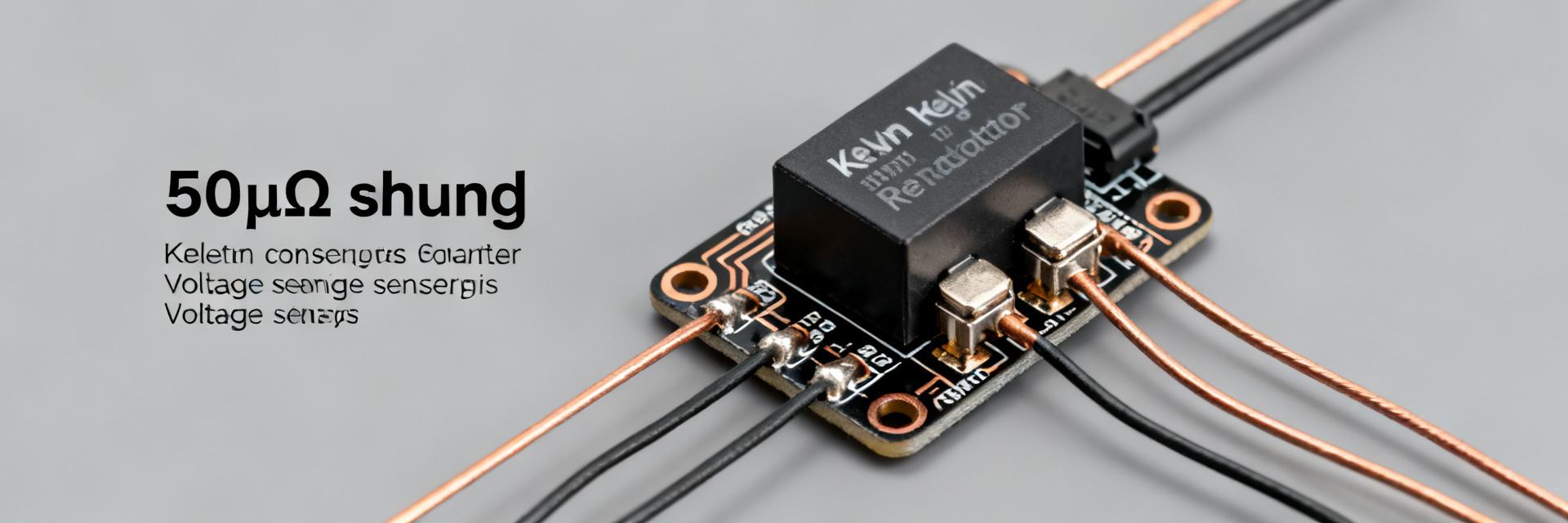
Procedure: apply a stable DC or reversal current, measure voltage with a nanovoltmeter via Kelvin connections, and average multiple reversals to cancel thermo-electric offsets. Instruments like milliohm meters or a precision current source plus DVM are standard. Select test current small enough to limit self-heating during baseline checks (e.g., 1–5 A) and larger currents for in-situ verification.
Installation tips: minimizing parasitics & thermal management
Minimize parasitic resistance with thick busbars or short heavy-gauge leads; place sense amplifier inputs as close as possible to the shunt terminals and use Kelvin sense wiring. For thermal management, mount to a thermally conductive plane or add heat spreaders; control terminal torque and use flat, clean mating surfaces to ensure low and repeatable contact resistance.
Application examples & procurement & compliance checklist (case + action)
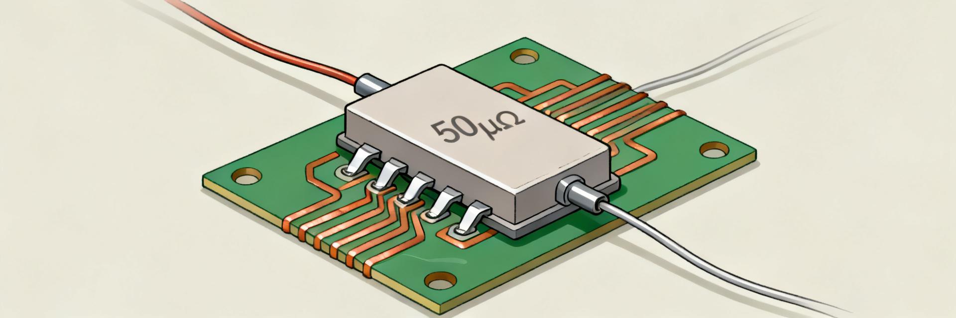
Representative sketches include a BMS current-sense loop feeding a differential amplifier (expect ~10 mV at 100 A), a PSU inrush monitor, and a bench load channel. In each case verify amplifier common-mode range, ADC resolution, and the effect of temperature on gain budgets. Procurement should demand mechanical drawings and lot test reports prior to purchase.
Representative application examples
Example: BMS sense at 150 A produces ~15 mV across 100µΩ; amplifier gain and offset need to yield a usable ADC input without saturating. For power-supply inrush detection a short burst measurement tolerates higher ΔT; for long-term monitoring use heatsinking and derating. Each application requires matching the measured thermal behavior to system tolerances.
Procurement checklist & compliance items before purchase
Checklist: confirm nominal R and tolerance, request TCR and thermal-rise curves, verify mechanical drawings and mounting torque, ask for lot sample test data, and confirm RoHS / safety notes. Insist on sample evaluation in your target fixture before full production buys to catch mounting or thermal mismatches early.
Summary
The HoFL3-8518 100µΩ shunt delivers low insertion loss and consistent thermal behavior when mounted per datasheet conditions; measured checks should verify resistance under load, TCR impact, and temperature rise to validate in-system accuracy. Use 4-wire Kelvin methods, control torque and thermal path, and request lot test reports. Next steps: obtain the manufacturer datasheet, run recommended Kelvin measurements, and validate the shunt in your specific target system.
Frequently Asked Questions
How do I verify the HoFL3-8518 100µΩ shunt resistance accurately?
Verify using a 4-wire Kelvin measurement with a calibrated current source and nanovoltmeter, use low test currents for baseline R and higher stabilized currents to show heating effects, reverse current polarity to cancel thermoelectric voltages, and document instrument uncertainty and ambient temperature for traceable results.
What torque and mounting steps are recommended for a HoFL3-8518 100µΩ shunt?
Use flat washers and controlled torque in the manufacturer’s recommended range (typically around 0.5–0.8 N·m for M3-terminals in similar parts), ensure clean flat contact surfaces, and re-check contact resistance after thermal cycling; insufficient torque increases contact resistance and measurement error.
How should I interpret datasheet specs vs measured specs for the HoFL3-8518 100µΩ shunt?
Compare datasheet R, TCR, rated current and thermal-rise conditions to your measured data under identical mounting and airflow; expect measured steady-state power and ΔT to be within roughly 10% of properly referenced datasheet values, and request lot test reports when discrepancies persist.
Why is a 100µΩ shunt value ideal for battery management systems (BMS)?
A 100µΩ shunt balances signal resolution with thermal dissipation. It yields a manageable 10 mV drop at 100 A, allowing precision measurement without excessive self-heating or voltage loss.