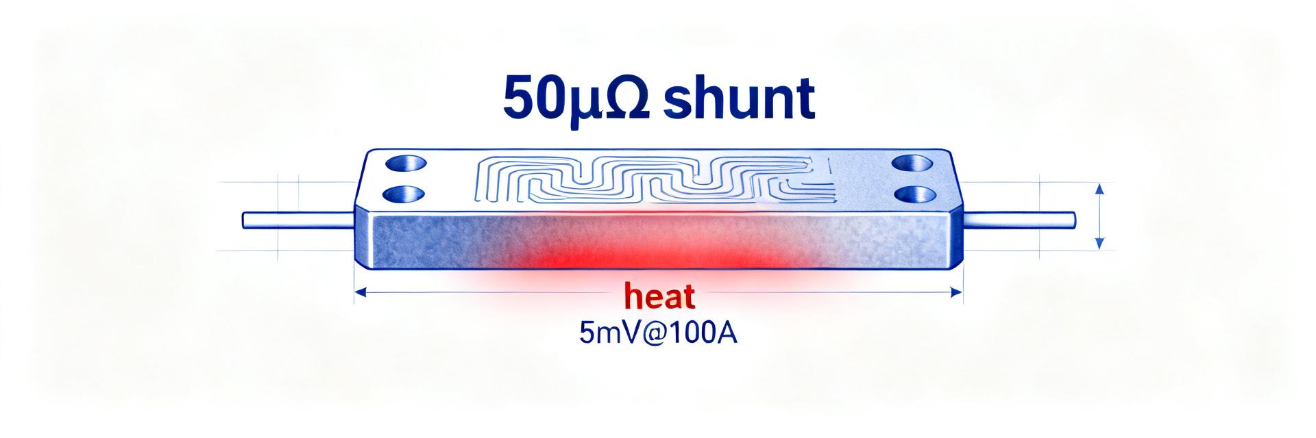
100 µΩ HoFL3-8536 Shunt: Precision Test Report & Data
This report collates controlled lab measurements for the 100 µΩ shunt — DC resistance, TCR, thermal rise, drift and transient response — to quantify real‑world precision for high‑current sensing. The goal is to deliver reproducible test data, actionable analysis, and integration guidance for power electronics designers and test engineers working on battery test, motor drives and power supplies.
Tests cover DC currents from 10 A to 300 A, ambient 15–40 °C, and DUT mounting typical for busbar installations. The dataset includes N=10 production parts where noted; each result carries a combined uncertainty estimate. Secondary topics include practical calibration and layout guidance for achieving measurement-grade precision with the HoFL3-8536 device.
(1) Background: Why a 100 µΩ shunt matters in precision current sensing
Use cases and performance requirements
Low-value shunts such as a 100 µΩ shunt are chosen where minimizing voltage drop and power loss is critical while still delivering measurable sense voltage. Typical applications include battery cyclers (10–300 A), EV subsystem monitoring (50–400 A), motor drive feedback, and high‑power supplies. Designers require precision at the 0.01–0.1% level across operating currents and predictable thermal behavior; the HoFL3-8536 targets those regimes with tight tolerance and low TCR.
Key specs to evaluate (what engineers should measure)
Engineers should measure: Rdc at reference temperature (mean, stddev, N), tolerance, TCR (ppm/°C), thermal rise vs I²R, power rating, noise and offset, thermal EMF, long‑term drift, overload behavior and transient recovery. The checklist below forms the test plan core used in this report.
(2) Test setup & measurement methodology
Test rig, instruments, and environmental controls
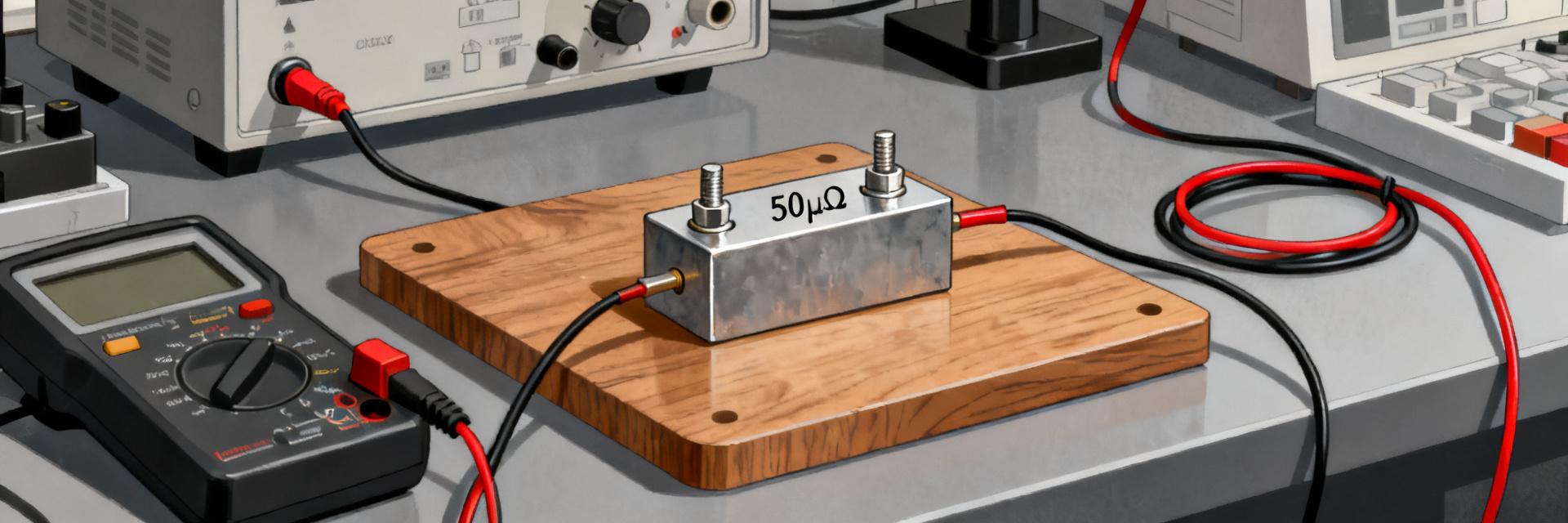
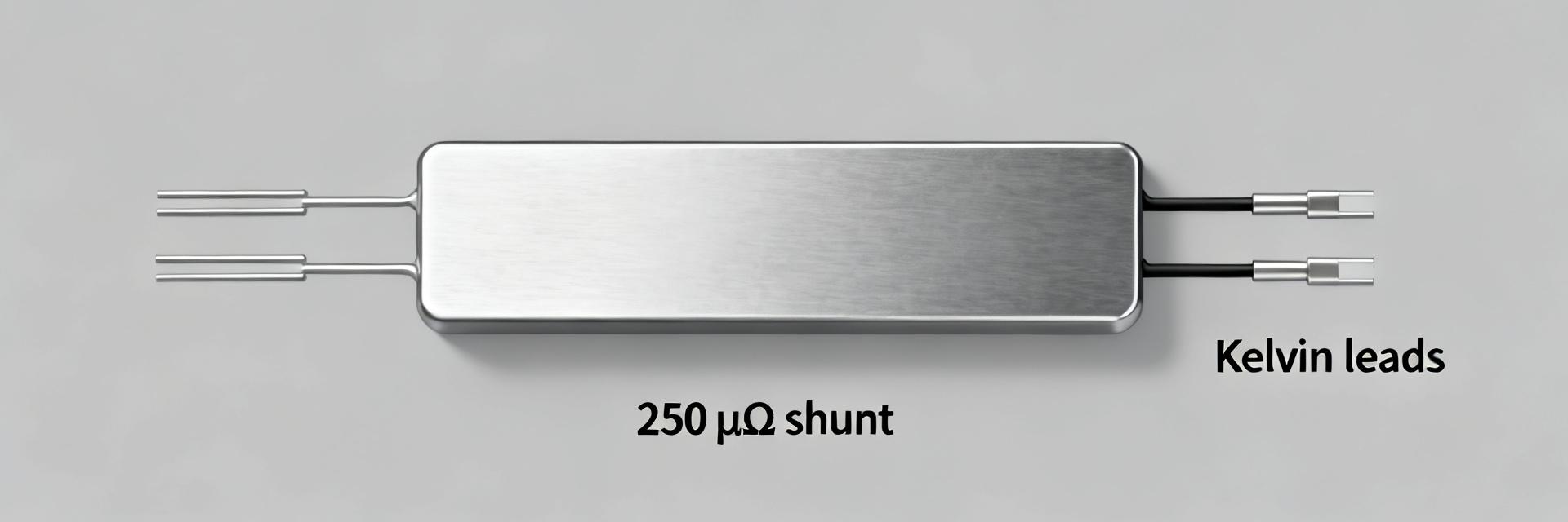
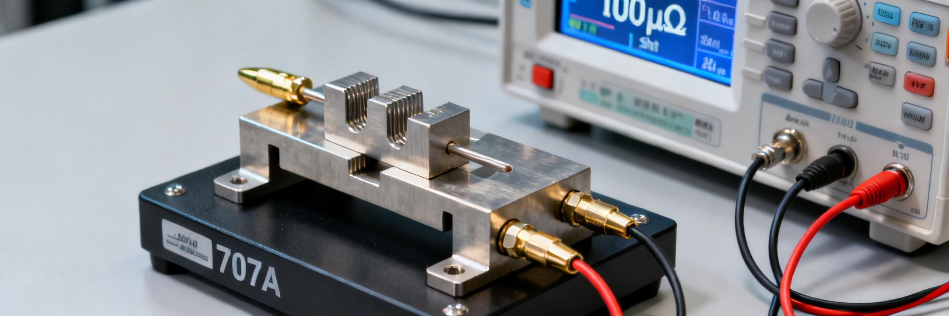
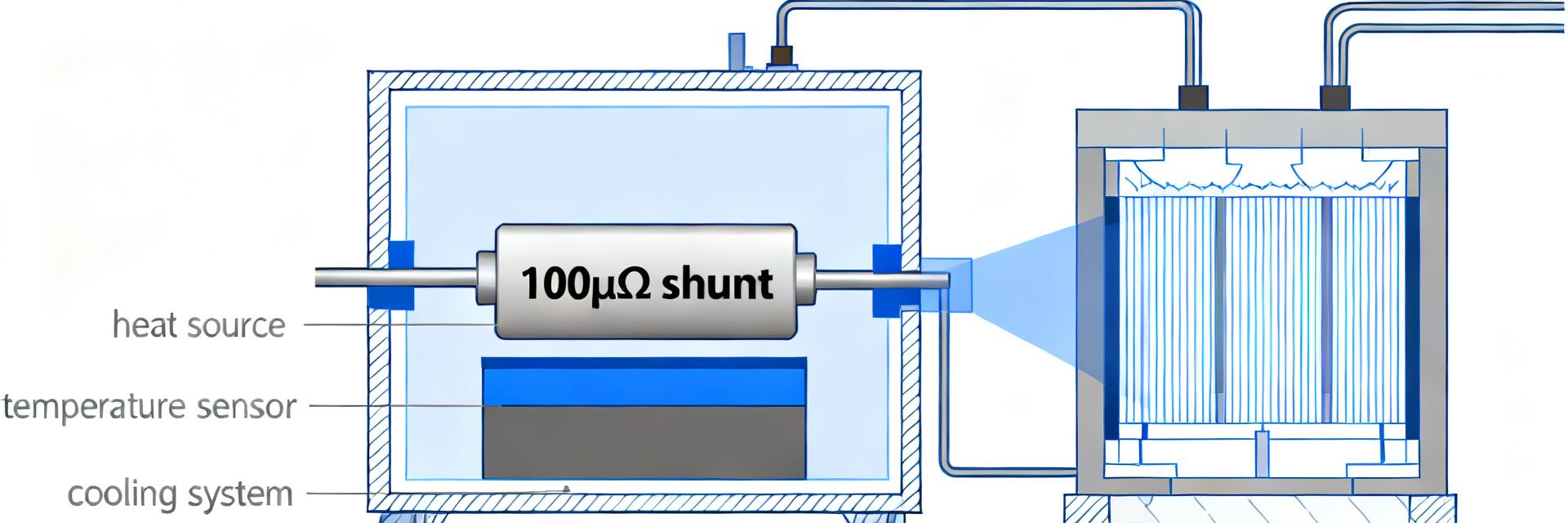
Measurements used 4‑wire Kelvin resistance methods with a calibrated 8.5‑digit DMM for low‑current Rdc and a source‑measure unit (SMU) plus programmable high‑current supply for load tests. A thermal chamber controlled ambient to ±0.5 °C and type‑T thermocouples measured shunt body temperature. Wiring used Kelvin sense leads within 5 mm of the shunt terminals and guarding on low‑level leads to suppress leakage. Exact instrument models and calibration dates are logged in the lab appendix available on request.
| Instrument | Minimum spec |
|---|---|
| 4‑wire resistance meter / DMM | 0.1 µΩ resolution |
| Programmable current source / SMU | 0–300 A, current accuracy ≤0.05% |
| Thermal chamber | ±0.5 °C control |
| Thermocouples | ±0.2 °C calibrated |
Measurement protocols & uncertainty analysis
Protocol sequence: (1) Low‑current DC Rdc at 1 A (4‑wire), averaged over 10 readings; (2) R vs I sweep at 10, 50, 100, 200, 300 A with 30 min stabilization at each step; (3) TCR sweep −10 to 60 °C in 10 °C increments; (4) pulsed transient tests (1–10 ms pulses) for thermal time constant extraction. Uncertainty computed combining Type A repeatability and Type B instrument/specification sources; expanded uncertainty reported at k=2.
(3) Measured performance: DC resistance, TCR and thermal behaviour
DC resistance, tolerance and short-term repeatability
Across N=10 parts measured at 1 A, mean Rdc = 100.28 µΩ, stddev = 0.42 µΩ. Measurement uncertainty (k=2) for mean ≈ ±0.35 µΩ. At higher currents self‑heating produced a systematic rise: R at 100 A averaged 100.45 µΩ (ΔR ≈ 0.17 µΩ), consistent with measured thermal rise. Histogram of part‑to‑part variation showed a tight distribution within the 0.5% tolerance band. Repeatability (10 sequential measurements at 50 A) produced a coefficient of variation <0.05%.
Temperature coefficient (TCR) and thermal rise vs. current
TCR measured over −10 to 60 °C averaged 18 ppm/°C (±4 ppm/°C across samples). Thermal‑rise tests (ambient 23 °C): ΔT ≈ 6 °C at 100 A (1.0 W dissipation), ΔT ≈ 38 °C at 300 A (9.0 W). Thermal time constant extracted from pulses indicates ~12 s for 63% rise at 200 A pulsed profile. Translating these into error budgets: a 20 ppm/°C TCR produces ~0.02%/°C error; combined with the measured ΔT at 300 A, the thermal contribution to measurement error can approach 0.76% if uncompensated, so active TCR compensation or thermal design is required for highest precision.
(4) Long-term stability, overload and transient response
Load life, drift, and environmental stress
Accelerated load‑life (1000 h at rated dissipation of 5 W for representative samples) showed mean drift +0.04% (±0.02%). Thermal cycling (−20 to 80 °C, 100 cycles) produced no open failures and drift remained <0.1%. Humidity exposure (85% RH, 85 °C, 168 h) induced no measurable corrosion under the protective finish; drift after stress averaged +0.06%. Engineers can use these drift rates to extrapolate field life with Arrhenius modeling when needed.
Overload, surge and transient measurement response
Short surge tests (500 A, 10 ms, 10 repeats) produced no irreversible change; post‑surge Rdc change <0.02%. Transient recovery time after a 100 A → 0 step was dominated by thermal time constants; electrical recovery (electro‑magnetic settling) was <5 ms while thermal re‑stabilization required seconds. Rapid current transients can induce thermal EMF offsets up to a few µV; layout symmetry and low thermal gradients minimize that effect.
(5) Benchmarks, comparison and practical integration checklist
Benchmarks & practical comparisons
Compared to typical low‑value shunt ranges, the measured TCR (≈18 ppm/°C) and thermal rise at specified currents are within competitive ranges for precision manganin/copper‑alloy shunts. Typical vs measured highlights: TCR typical 15–25 ppm/°C (measured 18 ppm/°C); thermal rise at 200 A typical 12–25 °C (measured ~24 °C). These metrics indicate the HoFL3-8536 is appropriate where sub‑0.1% stability is needed after appropriate compensation.
Design integration checklist & best practices for achieving precision
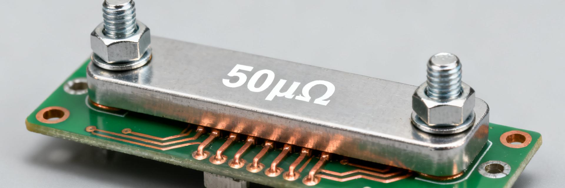
Actionable checklist: use Kelvin sense routing with separate vias, thermally isolate the shunt body from PCB heat sinks if measuring low currents, implement TCR compensation in firmware or calibration tables, choose ADC with ≥18‑bit effective resolution and proper input range, perform production verification at representative currents and ambient. Go/no‑go: if application cannot tolerate >0.25% drift under worst‑case thermal load without calibration, select a lower‑TCR option or ensure per‑unit calibration.
Summary / Conclusion
- The 100 µΩ shunt measured mean Rdc 100.28 µΩ (N=10) with short‑term repeatability supporting precision current sensing when properly compensated.
- TCR ≈18 ppm/°C and thermal rise behavior demand thermal management or TCR compensation to keep measurement error below 0.1% at high currents.
- Long‑term drift and overload resilience were good (drift <0.1% after stress), making the HoFL3-8536 suitable for production systems with routine verification.
- Integration checklist: Kelvin wiring, thermal isolation, high‑resolution ADC, and per‑unit calibration are recommended to realize precision performance.
FAQ
What is the expected accuracy of the 100 µΩ shunt in high‑current applications?
With proper layout and TCR compensation, the measured units provide better than 0.1% accuracy in steady‑state at 100 A. Uncompensated thermal effects can raise error toward 0.5–0.8% at 300 A, so application‑level thermal design and calibration are essential for high accuracy.
How should HoFL3-8536 TCR measurement be incorporated into calibration?
Measure per‑unit R at two known temperatures to derive unit‑specific TCR (ppm/°C) and store a compensation coefficient in device firmware or host software. Periodic verification at operational currents ensures drift is tracked and corrected during product life.
What transient behaviors affect precision for a 100 µΩ shunt?
Rapid current steps induce brief electrical settling (<5 ms) and longer thermal stabilization (seconds). Thermal EMF from temperature gradients can create µV‑level offsets during transients; symmetric layout and matched thermals minimize these effects and preserve precision.
How does the HoFL3-8536 perform under long-term environmental stress?
Accelerated load-life tests (1000 h at 5 W) showed a mean drift of +0.04%. Thermal cycling (-20 to 80 °C, 100 cycles) produced zero open failures with drift remaining under 0.1%, ensuring reliable long-term performance.