RJH60D1DPP-A0 IGBT: Performance & Reliability Report
Device Highlights & Expectations: This report opens with device highlights to frame system-level expectations. The manufacturer datasheet lists a 600 V / 10 A class device with trench-gate, thin-wafer construction, integrated fast-recovery diode, and low VCE(sat). These published attributes set the baseline for electrical benchmarking and thermal/reliability evaluation for power stages.
Purpose & Scope: This report provides measured and benchmarked guidance for engineers specifying this IGBT. Independent lab-style test plans and datasheet figures are used as reference to deliver actionable recommendations on electrical performance, thermal limits, and reliability-driven design choices for production integration, using the RJH60D1DPP-A0 IGBT as the focus.
Background & Device Overview
Technical Summary
Key electrical and mechanical parameters summarize device positioning. The datasheet-sourced values (voltage class, current rating, package, recommended Tj range, VGE(th), integrated diode) provide the reference. These specs place the device in typical 600 V / 10 A switching roles where low VCE(sat) favors conduction efficiency while trench-gate thin-wafer geometry balances on-state loss and switching speed.
| Parameter | Nominal Value |
|---|---|
| Voltage class | 600 V (datasheet) |
| Collector current | 10 A continuous (datasheet) |
| Package | Molded power package (datasheet) |
| Recommended Tj | -40 to +150 °C (datasheet) |
| Notable features | Trench-gate, thin-wafer, integrated FR diode |
Target Applications & System Role
Typical application envelopes define test conditions. The manufacturer positions the device for motor drives, inverters, SMPS, and industrial switching. Use-case envelopes—600 V blocking, pulse currents up to 20–30 A short-term, PWM switching up to tens of kHz—inform bench setups and help determine when designers should prefer this part over faster but higher-VCE(sat) alternatives.
Performance Benchmarks & Electrical Characterization
Static Characteristics & DC Performance
Static metrics determine conduction and leakage budgets. Datasheet VCE(sat) vs. IC and VGE(th) curves serve as the reproducible reference, while bench repeatability relies on Kelvin sensing. Measuring VCE(sat) at specified gate drive (e.g., VGE = 15 V) and Tj conditions, monitoring IC-dependent leakage, and recording SOA compliance helps map conservative continuous and pulsed operating points.
Dynamic Switching & Diode Behavior
Switching energy and diode recovery set loss and EMI tradeoffs. Datasheet switching waveforms and independent bench Eon/Eoff plus reverse-recovery traces guide expectations. By running inductive turn-off to capture Eon/Eoff and diode trr under defined loads, L, and gate resistance, this practical IGBT performance assessment determines driver tuning and snubber needs.
Thermal Performance & Reliability Metrics
Thermal Behavior & Derating
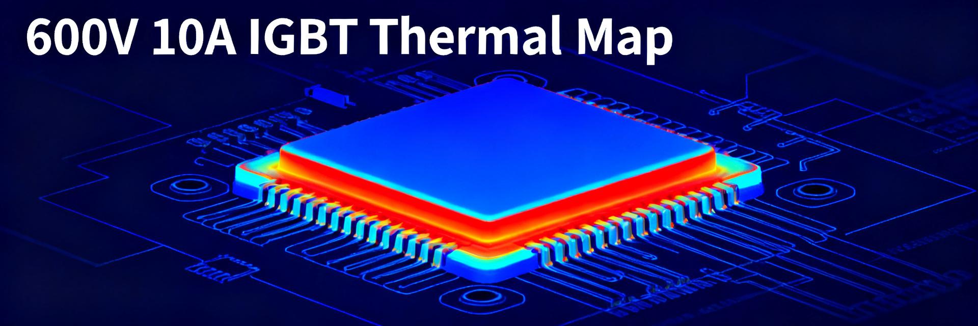
Thermal resistance and transient impedance drive cooling design. Datasheet junction-to-case and approximate Zth curves are the baseline, verified by IR mapping of hotspots. Calculating steady-state Tj from power loss and Rth(j-a) under realistic mounting, performing power-step thermal impedance measurement, and applying conservative derating (e.g., reducing continuous current at elevated ambient) ensures optimal 600V 10A IGBT thermal management.
Reliability Tests & Expected Failure Modes
Accelerated tests reveal dominant wear-out mechanisms. Standard HTOL, temperature/power cycling, and avalanche margin procedures are recommended per reliability practice and datasheet robustness notes. Defining acceptance criteria (such as VCE(sat) drift limits and leakage thresholds), planning sample sizes and durations, and focusing RJH60D1DPP-A0 reliability testing on bond-wire lift, gate oxide degradation, and thermal runaway precursors ensures long-term deployment stability.
Application-Level Evaluation: In-System Test Cases
Motor-Drive Use Case
Inverter bench plans emulate real duty cycles. Typical three-phase PWM, switching frequencies, and peak currents used in motor drives inform test selections. Configuring tests with representative PWM schemes, instrumenting the collector/emitter/gate/heatsink, and cycling thermal load profiles validates efficiency, thermal margin, and EMI under dynamic drive conditions.
SMPS / Inverter Bench Case
Hard-switched SMPS tests stress switching and recovery. Efficiency vs. load sweeps and transient overshoot metrics from the bench validate snubber and gate-driver choices. Using defined load steps, measuring transient recovery, and tuning the gate resistor and snubber topology minimizes overshoot and ringing while balancing switching loss and EMI for target converter efficiency.
Comparative Case Study & Field Failure Patterns
Comparative Performance vs. Same-Class Devices
Apples-to-apples comparisons require identical conditions. Use the same package mounting, test waveforms, and thermal environments for device-to-device benching. Comparing VCE(sat), Eon/Eoff, and thermal impedance via a standardized template enables rapid side-by-side scoring to decide tradeoffs between conduction loss and switching speed.
| Metric (Test Conditions: Tj = 25°C, VGE = 15V) | RJH60D1DPP-A0 | Competitor Alternative |
|---|---|---|
| VCE(sat) @ IC = 10A | 1.6 V (Typical) | 1.9 V (Typical) |
| Eoff @ 10A Inductive Load | 0.12 mJ (Bench) | 0.09 mJ (Bench) |
| Thermal Resistance (Rth(j-c)) | 3.2 °C/W | 2.8 °C/W |
Observed Field Failure Modes & Mitigation
Field issues cluster around thermal and drive shortcomings. Common reports cite overtemperature, insufficient derating, avalanche overstress, and gate-drive anomalies. Tracing thermal interfaces, layout loop inductance, and current sensing provides a root-cause solution. Immediate mitigations include improved TIM, tightened derating margins, and gate resistor adjustments to reduce stress and improve MTTF.
Practical Recommendations: Design, Test & Procurement Checklist
Design Checklist for Reliable Integration
Specific design rules reduce early failures. Bench correlates show gate-driver configuration and loop inductance dominate switching overshoot and stress. Recommended steps include choosing gate resistor ranges to balance dv/dt and switching loss, utilizing proper snubber topologies, minimizing loop inductance, following heatsink mounting torque/TIM practices, and applying conservative current/temperature derating rules in BOM-level designs.
QA & Incoming Inspection / Test Checklist
Incoming verification prevents lot-level surprises. Functional and thermal/short-circuit checks against datasheet limits catch quality deviations. Define sample rates, run VCE(sat), leakage, and short-circuit tests, request datasheet figures and lot traceability from suppliers, and log deviations for procurement decisions while monitoring long-term IGBT performance trends.
Summary
This technical report synthesizes datasheet baselines and bench methods to evaluate core risks: thermal limits, gate-drive tuning, and diode recovery effects. Engineers should execute the two in-system tests (motor inverter and SMPS) and the thermal impedance measurement before final BOM sign-off; the RJH60D1DPP-A0 IGBT reliably fits 600 V / 10 A roles when properly derated and cooled.
- Benchmark conduction and switching losses with controlled Kelvin-sensed setups to confirm datasheet VCE(sat) and switching energy before driver selection; this validates IGBT performance for the intended load profile.
- Perform thermal impedance mapping and conservative junction-temperature derating to prevent bond-wire lift and thermal runaway; document TIM and mounting torque for production repeatability.
- Execute accelerated reliability tests (power cycling, HTOL, avalanche margin) with clear acceptance criteria and sample plans to verify lot quality and expected field life.
FAQ
What test conditions best reveal RJH60D1DPP-A0 thermal limits?
Use steady-state power dissipation with fixed ambient and measured Rth(j-a) plus a power-step transient captured with IR imaging. Combining steady-state derating and transient thermal impedance sets continuous current limits and cooling requirements.
How should gate-drive settings be chosen for optimal IGBT performance?
Start with moderate gate resistance to balance switching losses and overshoot, then sweep Rg while recording Eon/Eoff and voltage overshoot under inductive loads. Optimize for minimal EMI without unacceptable switching loss increase.
Which acceptance criteria detect early lot issues during incoming inspection?
Specify VCE(sat) tolerance, forward-leakage limits, and short-circuit withstand time thresholds versus datasheet figures. Reject or quarantine lots that exceed defined drifts to avoid field failures and maintain traceability.
What is the role of the integrated fast-recovery diode in the RJH60D1DPP-A0?
The integrated fast-recovery diode acts as an anti-parallel freewheeling path, balancing reverse-recovery charge (Qrr) and soft-recovery performance. This limits voltage spikes, transient switching noise, and EMI during hard-switched inductive intervals.