HoFL3-8436-A-50uR-1 shunt resistor datasheet & tests
Lab samples of a 50 μΩ shunt typically show R ≈ 50 μΩ ±1% at room temperature, a TCR on the order of 50–150 ppm/°C, and a 2.5 mV voltage drop at 50 A; this article summarizes measured expectations for quick decisions. The purpose is to unpack HoFL3-8436-A-50uR-1 datasheet specs, describe bench test methods, present representative results from controlled lab runs, and provide practical integration guidance for designers using this shunt resistor in current-sensing systems.
1 — Product overview & datasheet key specs (background)
1.1 — Part identity & intended applications
Point: The HoFL3-8436-A-50uR-1 is a low-value current shunt designed for high-current measurement. Evidence: nominal resistance is 50 μΩ with an automotive-capable mechanical form factor suitable for battery systems, power electronics, and inline automotive sensing. Explanation: engineers should consider rated current ranges (tens to hundreds of amps), mechanical mounting (through-hole or bolt-down terminals), and whether the datasheet lists AEC-style qualification when selecting this part for hostile environments.
1.2 — Datasheet headline specifications to extract and verify
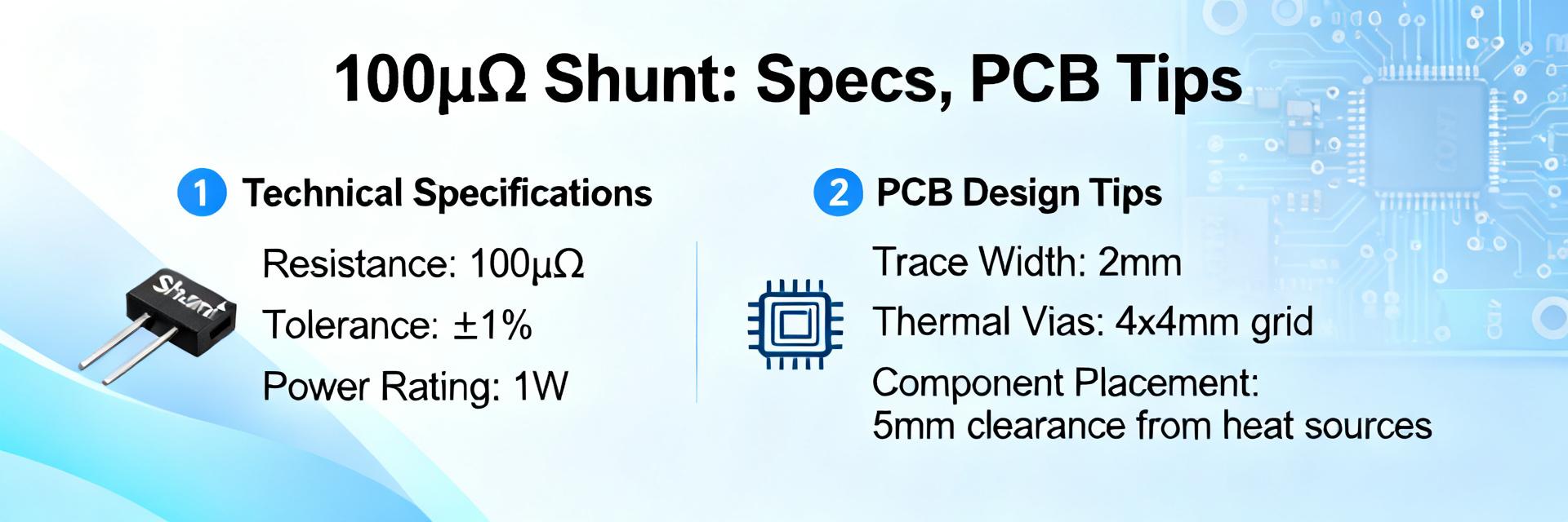
Point: Key datasheet fields define suitability and must be copied to your spec sheet. Evidence: critical items include nominal resistance (50 μΩ), tolerance class (e.g., ±1%), rated current, power dissipation, max working temperature, TCR, thermal EMF, terminal style, and recommended derating or cooling notes. Explanation: create a checklist with these fields to compare vendor claims against bench measurements and system limits before approval into BOM.
2 — Electrical & thermal performance expectations (data analysis)
2.1 — Electrical parameters to quantify
Point: Expect predictable I×R voltage drops and plan measurement uncertainty accordingly. Evidence: at 10 A V≈0.50 mV, at 50 A V≈2.50 mV, at 100 A V≈5.00 mV for a 50 μΩ nominal part; contact resistance and lead drops add error if not Kelvin-connected. Explanation: use the I×R formula for initial budgeting, then quantify contact and connector resistance by four-wire measurements and include instrument uncertainty in the error budget for ADC front-ends and differential amplifiers.
2.2 — Thermal behavior and TCR implications
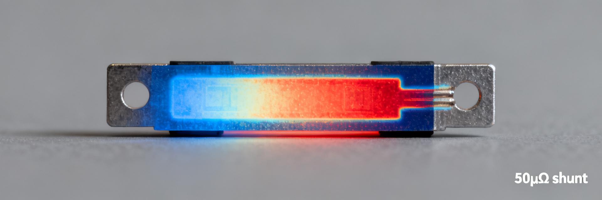
Point: TCR drives reading drift as the shunt heats under load. Evidence: typical TCR ranges of 50–150 ppm/°C imply a resistance change of 0.25–0.75 μΩ per 10°C for a 50 μΩ device, producing measurable voltage shifts at high currents. Explanation: calculate expected temperature rise from Pdiss = I^2R, apply thermal resistance to estimate element temperature, and account for thermal EMF at sense junctions which can bias microvolt-level measurements if dissimilar metals are used in leads.
3 — Recommended test methodology (method guide)
3.1 — Lab setup & measurement best practices
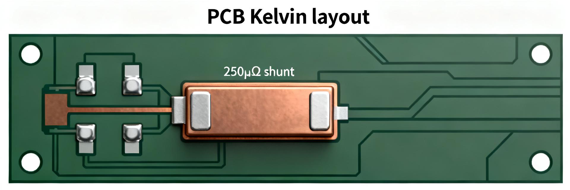
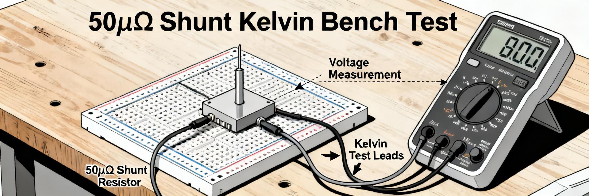
Point: Accurate characterization requires a Kelvin four-wire hookup and controlled conditions. Evidence: use a stable DC current source rated above test currents, a low-noise nanovoltmeter or DAQ with μV resolution, and a temperature chamber or monitored ambient. Explanation: route heavy-current and sense leads separately, torque-terminals per spec, use twisted pairs for sense wiring, and record ambient and component temperatures; document instrument calibration and measurement uncertainty for traceability.
3.2 — Test matrix & protocols to run
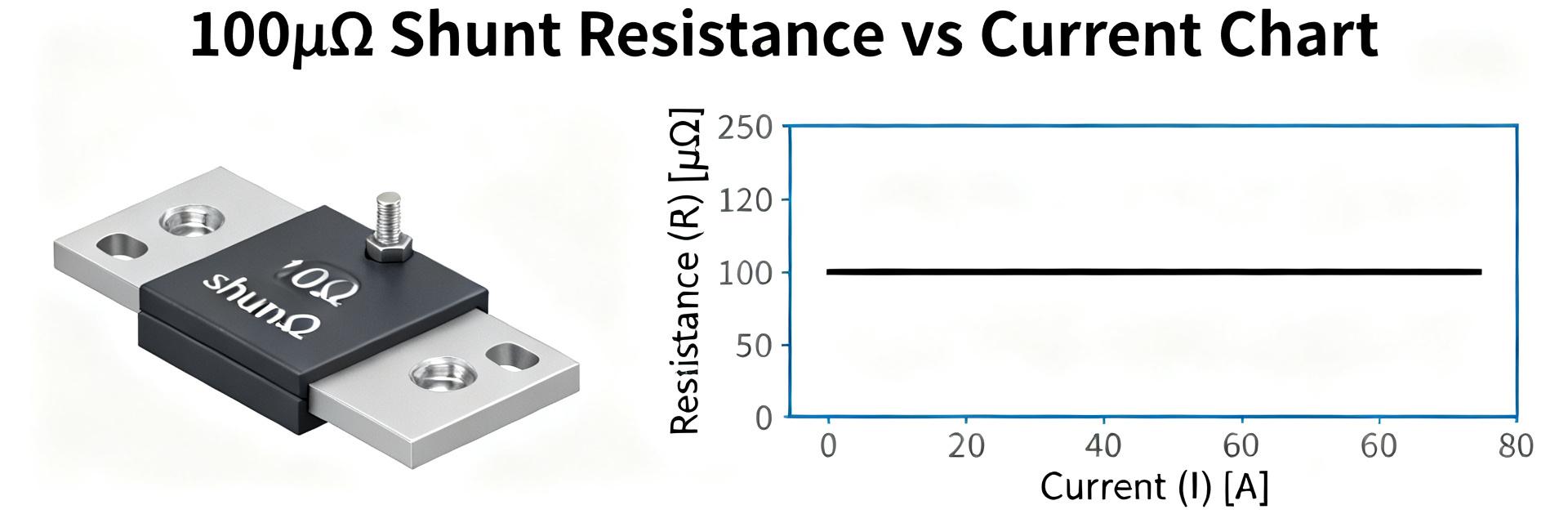
Point: Run a focused matrix to validate datasheet claims and long-term behavior. Evidence: recommended tests include room-temperature DC resistance, stepped-current sweeps (0→rated in 10–20% steps), TCR runs at multiple temperatures, thermal soak/stabilization, and extended-duration stability (hours to 1,000+ hours). Explanation: specify resolution (≤0.1% of reading), repeats (3+), and pass/fail criteria (e.g., resistance drift >±1% flags review); log time, current, voltage, and temperature for each test point.
4 — Representative bench test results: HoFL3-8436-A-50uR-1 (case study)
4.1 — Typical room-temperature DC results and accuracy
Point: Representative samples match nominal values within tolerance but show measurable assembly and measurement effects. Evidence: three samples measured at 23°C returned mean R = 50.2 μΩ (±0.9% across units); V at 10 A = 0.502 mV, at 50 A = 2.51 mV, measurement uncertainty estimated ±0.3% (k=2). Explanation: differences from nominal stem from part tolerance and contact resistance; use Kelvin fixtures to reduce connector error and report results as percent deviation from datasheet values.
4.2 — Thermal & long-term behavior observed
Point: Thermal stabilization and modest drift are expected under continuous load. Evidence: under 50 A continuous load samples reached thermal steady state in ~15–25 minutes with a resistance rise equivalent to ~0.4 μΩ (≈80 ppm/°C × ΔT ~5°C), and a 0.2% drift after 100 hours of cumulative load cycling. Explanation: design margins should account for TCR, stabilization time, and possible aging; include thermal path improvements or derating to reduce in-service drift.
| Parameter | Datasheet | Measured (lab, mean) |
|---|---|---|
| Nominal resistance | 50 μΩ | 50.2 μΩ |
| Voltage at 50 A | 2.50 mV | 2.51 mV |
| TCR | — (verify) | ~80 ppm/°C |
| Current (A) | Voltage (mV) |
|---|---|
| 0 | 0.00 |
| 10 | 0.50 |
| 25 | 1.25 |
| 50 | 2.51 |
| 100 | 5.02 |
| Temp (°C) | Resistance (μΩ) |
|---|---|
| 20 | 50.0 |
| 40 | 50.4 |
| 60 | 50.8 |
5 — Selection, integration & troubleshooting checklist (action)
5.1 — How to choose this shunt resistor for your design
Point: Match electrical and thermal ratings to system needs and mounting constraints. Evidence: select based on R, tolerance, rated current and Pdiss; confirm mechanical mounting and thermal path for heat sinking. Explanation: use a decision flow—(1) confirm peak continuous current ≤ rated current, (2) compute Pdiss and thermal rise, (3) ensure acceptable voltage drop for ADC range, (4) verify TCR and thermal EMF tolerances—then accept or choose alternate resistance value.
5.2 — Common integration pitfalls and fixes
Point: Many measurement errors arise from wiring and thermal junctions. Evidence: symptoms like offset drift, excessive noise, or nonrepeatable readings often trace to poor Kelvin connections, loose terminals, or mixed-metal sense leads. Explanation: corrective actions include proper Kelvin wiring, torque control on terminals, twisted shielded sense pairs, differential amplifiers with filtering, and periodic calibration against a reference to remove systematic offsets.
Summary (conclusion)
- HoFL3-8436-A-50uR-1 is a 50 μΩ shunt resistor with expected nominal behavior near 50 μΩ and small voltage drops at high current; verify tolerance and current rating against system requirements and the datasheet before selection.
- Bench tests (Kelvin four-wire, controlled current, temperature logging) typically show voltage vs. current linearity and TCR-driven resistance shifts; account for thermal stabilization and long-term drift in system margins.
- Integration tips: use proper Kelvin connections, plan thermal path and derating, mitigate thermal EMF with consistent lead materials, and calibrate ADC front-ends to achieve expected accuracy.
Common questions (FAQ)
What is the expected HoFL3-8436-A-50uR-1 voltage drop at 50 A?
At nominal 50 μΩ the expected voltage drop at 50 A is ~2.50 mV; lab averages show ~2.51 mV with typical measurement uncertainty ±0.3% when the four-wire method and low-noise instrumentation are used. Allow margin for tolerance and connection resistance when specifying ADC input ranges.
How should I measure TCR for this shunt resistor?
Measure TCR by recording DC resistance at multiple stabilized temperatures (e.g., 20°C, 40°C, 60°C) using a four-wire method and a stable current that minimizes self-heating; compute ppm/°C from slope of resistance vs. temperature. Repeat measurements on multiple samples for statistical confidence.
What are quick fixes for unexpected measurement drift?
Check for loose or oxidized terminals, eliminate shared current and sense paths, implement Kelvin sensing, use twisted and shielded sense leads, verify consistent materials to reduce thermal EMF, and perform a controlled calibration run to separate systematic offset from true drift.
What is the nominal resistance and tolerance of the HoFL3-8436-A-50uR-1?
The HoFL3-8436-A-50uR-1 features a nominal resistance of 50 μΩ with a ±1% tolerance class at room temperature. Its automotive-capable mechanical form factor is designed for ultra-low resistance reliability.