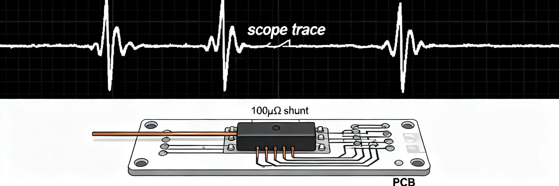
Current Sense Resistor 250 µΩ: Performance Specs & Datasheet
In many high-current systems a 250 µΩ resistor produces only 25 mV at 100 A but still dissipates 2.5 W—small voltages and significant heat make part choice and integration critical. This guide explains how to read a 250 µΩ current sense resistor datasheet, interpret performance specs, and apply practical design and test steps for reliable, accurate current measurement in US industry designs. Example part codes such as HoFL3-8518-B-250uR-0.5% are typical identifiers you will encounter on datasheets and procurement lists.
Readers will find formulas, example calculations, datasheet fields to prioritize, layout and amplifier guidance, and a bench-test checklist. The content is aimed at engineers specifying shunts or low-ohm chip resistors for battery, motor-drive, and power-conversion applications where millivolt-level signals and thermal limits govern accuracy and reliability.
1 — Why the 250 µΩ current sense resistor matters (Background)
Key electrical parameters to understand
Point: The nominal value 250 µΩ yields V = I·R, so 50 A -> 12.5 mV, 100 A -> 25.0 mV, 200 A -> 50.0 mV. Evidence: Pdiss = I²·R gives 50 A -> 0.625 W, 100 A -> 2.5 W, 200 A -> 10 W. Explanation: Low voltage levels demand low-noise amplification and Kelvin sensing; power dissipation drives package selection and derating decisions.
Typical form factors and materials (what to expect on datasheets)
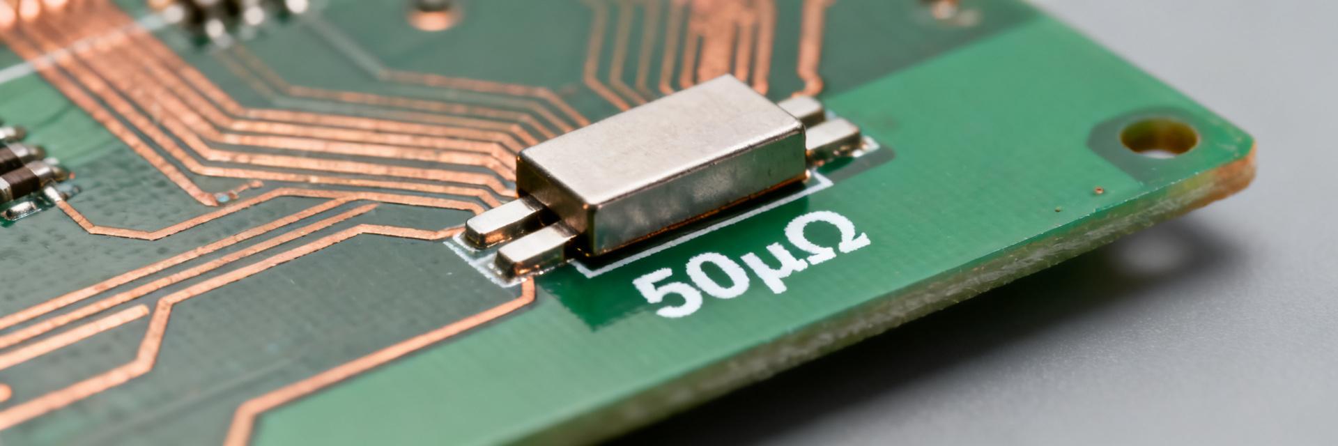
Point: Datasheets list package type (low-ohm metal strip, bolted shunt, or SMD low-ohm chip), material, and mounting notes. Evidence: Materials such as copper alloys, manganin-like alloys, or nickel-chrome variants are shown with TCR and stability data. Explanation: Choose material for low TCR and low thermal EMF if accuracy across temperature matters; mechanical mounting affects thermal path and long-term drift.
| Current (A) | Voltage (mV) | Power (W) |
|---|---|---|
| 50 | 12.5 | 0.625 |
| 100 | 25.0 | 2.5 |
| 200 | 50.0 | 10.0 |
2 — Performance specs decoded: accuracy, thermal behavior, and limits (Data analysis)
How tolerance & TCR affect measurement accuracy
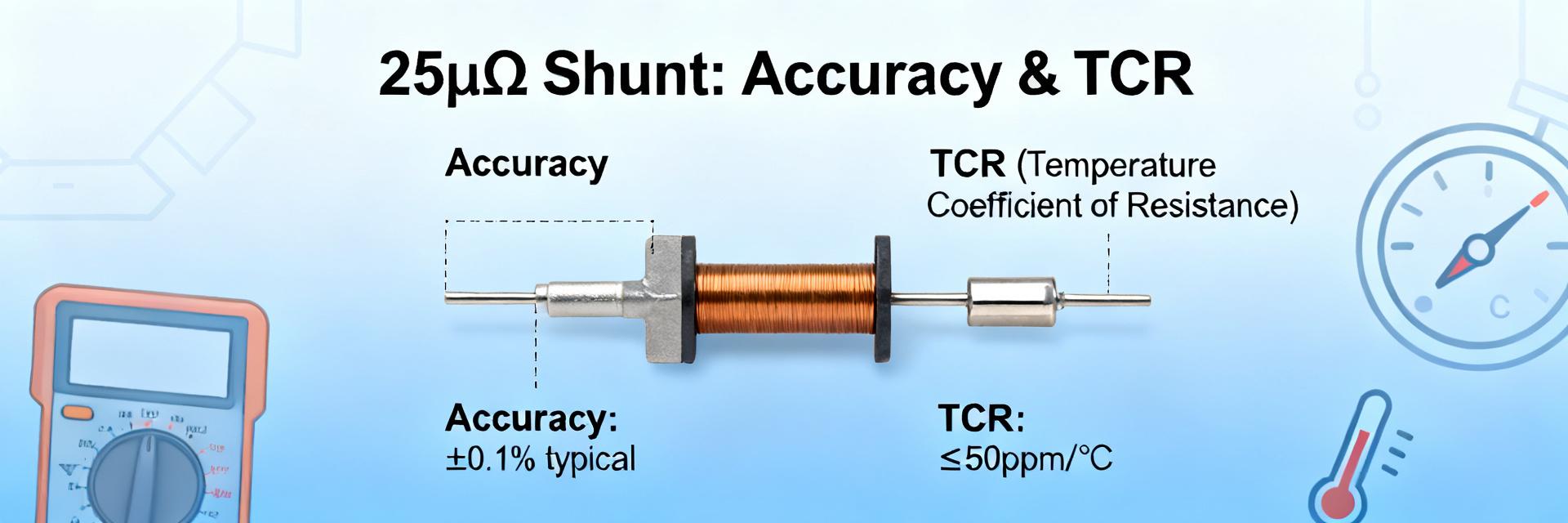
Point: Tolerance and TCR combine to create total resistance error over temperature. Evidence: A ±1% tolerance at reference temperature plus ±50 ppm/°C TCR across −40 °C to +85 °C yields additional ΔR = TCR·ΔT; for ΔT = 125 °C, ΔR ≈ 0.00625% from TCR alone, but worst-case additive error relative to tolerance can exceed application budgets. Explanation: Express errors both in ppm and percent; convert ppm to percent by (ppm·ΔT)/1e4 for quick comparison and set target specs per application class.
Power rating, derating curves, and thermal resistance
Point: Rated power is often specified at a reference ambient, typically with a derating curve to maximum operating temperature. Evidence: Use Pdiss = I²·R to calculate steady-state dissipation and compare to derated rating; check RθJA or equivalent thermal resistance on the datasheet to estimate temperature rise: ΔT ≈ Pdiss·RθJA. Explanation: If calculated junction/element temperature exceeds allowable limits, select higher-power package or enforce forced cooling or lower continuous current.
3 — Datasheet deep-dive: fields you must read (Datasheet)
Critical datasheet entries and why they matter
Point: Mandatory fields include nominal resistance @ reference temp, tolerance, TCR (ppm/°C), rated power & derating, maximum continuous current, measurement method (4-terminal vs 2-terminal), parasitic inductance, mechanical drawing, soldering notes, and reliability data. Evidence: Datasheet entries for these fields define accuracy, thermal limits, and integration constraints. Explanation: Prioritize parts with explicit 4‑terminal measurement instructions, clear derating curves, and measured parasitic inductance if used in fast current transients.
How to compare parts using datasheet numbers
Point: Normalize datasheet numbers before comparison. Evidence: Convert all power ratings to a common reference temp, calculate expected ΔR at target operating temperature using TCR, convert max continuous current to expected voltage drop, and verify mounting clearances. Explanation: Red flags include missing derating curves, unspecified TCR, or ambiguous measurement method; discard ambiguous datasheets or request clarification from supplier technical documents.
4 — How to integrate a 250 µΩ current sense resistor into your design (Method/Guidance)
Layout, Kelvin sensing, and mechanical considerations
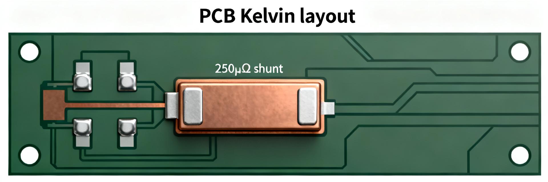
Point: Proper PCB and mechanical integration preserves accuracy and reliability. Evidence: Use four-terminal (Kelvin) connections with short sense traces, keep sense traces away from large return currents, place amplifier close to sense resistor, and use thick copper for the main current path. Explanation: For bolted shunts ensure proper torque and flat contact surfaces; thermal anchoring to chassis or heatsink reduces local temperature rise and long-term drift.
Front-end amplifier, filtering, and ADC considerations
Point: Match amplifier and filter design to millivolt-level signals. Evidence: Select amplifiers with low input offset, appropriate common-mode range, and gain accuracy; calculate required gain G = ADC_fullscale / V_sense_max to use ADC range while leaving headroom for offsets. Explanation: Use RC filtering to limit bandwidth and improve SNR, but balance against transient tracking needs; consider correlated double-sampling or oversampling if ADC resolution is limiting.
5 — Test, validation, and selection checklist (Actionable)
Bench tests and expected measurement results
Point: Bench validation confirms datasheet claims and integration quality. Evidence: Perform four-wire resistance check at room temp, run controlled current sweeps logging voltage and temperature, use thermal imaging to locate hotspots, and execute repeatability cycles. Explanation: Pass criteria include measured resistance within tolerance and thermal drift within datasheet long-term drift; document failure margins and corrective actions.
Common failure modes, troubleshooting, and final procurement checklist
Point: Typical failures stem from thermal overload, poor Kelvin connections, mechanical loosening, or corrosion. Evidence: Procurement checklist should mandate nominal 250 µΩ, tolerance target (e.g., 0.5% or better), TCR max, rated power at specified temp, maximum continuous current, 4-terminal measurement method, mounting footprint, derating curves, and required qualification tests. Explanation: Include assembly notes and torque specs with purchase order to prevent installation-induced errors.
Summary
- Choose a current sense resistor by balancing nominal 250 µΩ value, tolerance, and TCR to keep millivolt signals within amplifier and ADC capabilities while minimizing temperature-induced error.
- Read the datasheet fields carefully—rated power, derating curve, RθJA, measurement method (4-terminal), and parasitic inductance determine usable current range and accuracy.
- Integrate with Kelvin sensing, short sense traces, and a matched low-offset amplifier; compute gain using G = ADC_fullscale / V_sense_max to preserve SNR and accuracy.
- Validate with four-wire resistance checks, controlled current sweeps, thermal imaging, and repeatability tests before final procurement and production acceptance; reference part codes like HoFL3-8518-B-250uR-0.5% when documenting requirements.
Frequently Asked Questions
What accuracy can I expect from a 250 µΩ current sense resistor?
Expect base accuracy determined by tolerance and TCR; for example a 0.5% tolerance resistor with 50 ppm/°C TCR will show initial error near 0.5% plus temperature-dependent drift. System-level accuracy also depends on amplifier offset, ADC resolution, and wiring; perform system-level calibration to meet tight budgets.
How do I read the datasheet to find thermal limits for a 250 µΩ resistor?
Check the rated power and derating curve, look for RθJA or element-to-ambient thermal resistance, and note the reference ambient temperature for the rating. Calculate Pdiss = I²·R and multiply by RθJA to estimate temperature rise; ensure the resulting element temperature stays within specified limits under worst-case conditions.
When should I require a 4-terminal measurement method on the datasheet?
Require 4-terminal (Kelvin) measurement when the sense voltage is millivolts and contact or trace resistance would materially affect accuracy. The datasheet should state recommended measurement method and provide a mechanical drawing showing separate sense and load terminals; specify 4-terminal in procurement to avoid ambiguity.
How does parasitic inductance in a 250 µΩ resistor impact dynamic current measurement?
At 250 µΩ, parasitic inductance (typically under 3 nH for SMDs) can dominate the impedance at high frequencies. For fast switching transients (such as in GaN or SiC motor drives), di/dt induces an error voltage (V = L * di/dt) that corrupts the pure resistive drop. Designers must select low-inductance shunt geometries and match filter time constants.