HoFL3-8436-B 50µΩ Shunt: Complete Performance Datasheet
Point: The HoFL3-8436-B 50µΩ shunt delivers a measurable 5.0 mV at 100 A and dissipates 0.5 W at that current — numbers that define its suitability for high-current battery and power-monitoring systems. Evidence: that sensing scale maps directly to common ADC ranges and power budgets in battery management and power-conversion applications. Explanation: this datasheet-style guide documents electrical, thermal and test methods so engineers can validate performance against system requirements and reproduce datasheet numbers.
Point: Purpose and scope are to provide a complete, testable datasheet and bench guide. Evidence: the article covers nominal specs, I–V characterization, thermal behavior, reliability test protocols, step-by-step bench procedures and a concise selection checklist. Explanation: readers will obtain actionable acceptance criteria and templates to integrate the device into systems and to confirm measured results match datasheet expectations.
Product overview & nominal specifications (background)
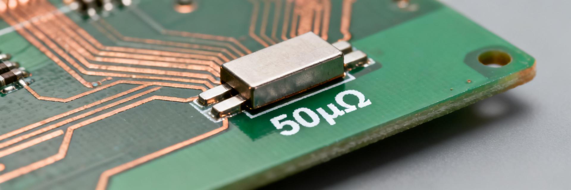
Key electrical specs — nominal resistance, tolerance, power rating, temp. coefficient
Point: Nominal resistance and output scale define selection and ADC interfacing. Evidence: nominal R = 50 µΩ; tolerance options commonly offered ±0.5% or ±1%; recommend continuous dissipation limit ~1 W when properly cooled, typical TCR ~50–150 ppm/°C depending on alloy. Explanation: present these fields clearly in a datasheet row so designers see Vdrop and P at common currents and choose sensing front-end gain and ADC range accordingly.
| Current (A) | Vdrop (mV) | P diss. (W) |
|---|---|---|
| 10 | 0.50 | 0.005 |
| 50 | 2.50 | 0.125 |
| 100 | 5.00 | 0.500 |
| 200 | 10.00 | 2.000 |
Point: Use the descriptor "50µΩ shunt resistor" on the datasheet mechanical and electrical summary line. Evidence: that wording immediately conveys the low-ohm class and sensing scale to procurement and system engineers. Explanation: include tolerance, rated power, and TCR in the same top-line block so engineers can quickly match to ADC and thermal constraints.
Mechanical, pinout and packaging details
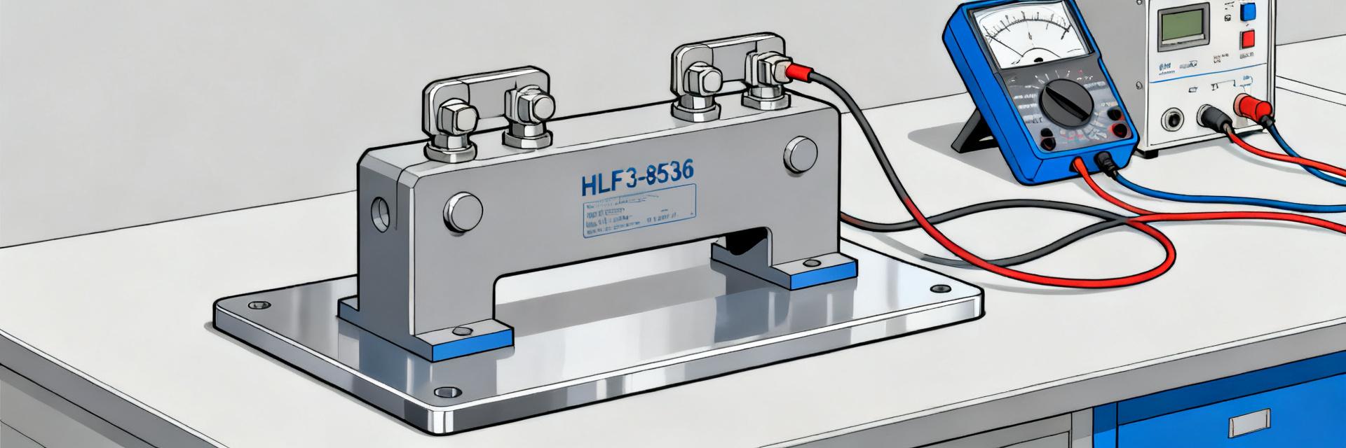
Point: Mechanical details govern mounting, torque and thermal path. Evidence: typical package is a metal-strip shunt with two bolted terminals; suggested mounting pitch 64 mm (if applicable) and terminal hardware rated to specified torque. Explanation: provide a drawing with critical dimensions, recommended PCB/fixture footprint, terminal type, torque spec and mechanical tolerances (±0.2 mm) so installers maintain low contact resistance and consistent thermal coupling.
Electrical performance data — measurements & characterization (data analysis)
Point: Characterization establishes linearity, accuracy and uncertainty for HoFL3-8436-B across the operating range. Evidence: run V vs I from 0–rated and capture deviations vs ideal linear fit; four-wire Kelvin measurements with sub‑microvolt resolution reveal millivolt-level behavior. Explanation: include an accuracy table, linearity % deviation and an uncertainty budget to quantify measurement confidence for system-level error budgeting.
I–V linearity, measurement results and accuracy
Point: Linearity testing verifies proportional Vdrop to current and identifies nonlinearity at high self-heating. Evidence: test points at 0, 10, 50, 100, 150, 200 A using a stable current source; expect millivolt-range signals and target resolution ≤1 µV to resolve 0.02% at 100 A. Explanation: report V vs I table and a plot showing % deviation from ideal, and state instrumentation (four-wire source measure unit, differential ADC) used in test.
Resistance tolerance, thermal EMF and temperature dependence
Point: Resistance vs temperature and thermal EMF determine measurement drift and offsets. Evidence: measure DC resistance at ambient and under self-heating; record TCR (ppm/°C) and thermal EMF (<1 µV/°C typical for metal strip). Explanation: include a small table of typical vs max limits, a drift curve (resistance % vs temperature) and recommended methods to compensate in firmware or calibration.
Thermal behavior & reliability (data analysis)
Thermal resistance, dissipation limits and derating
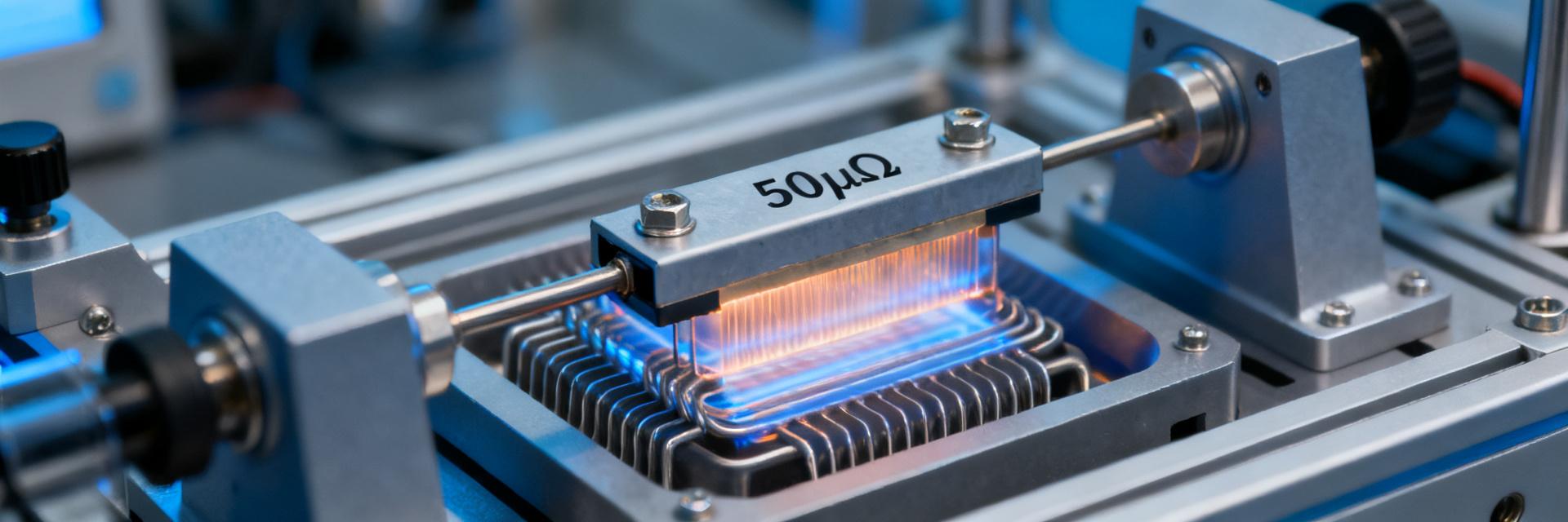
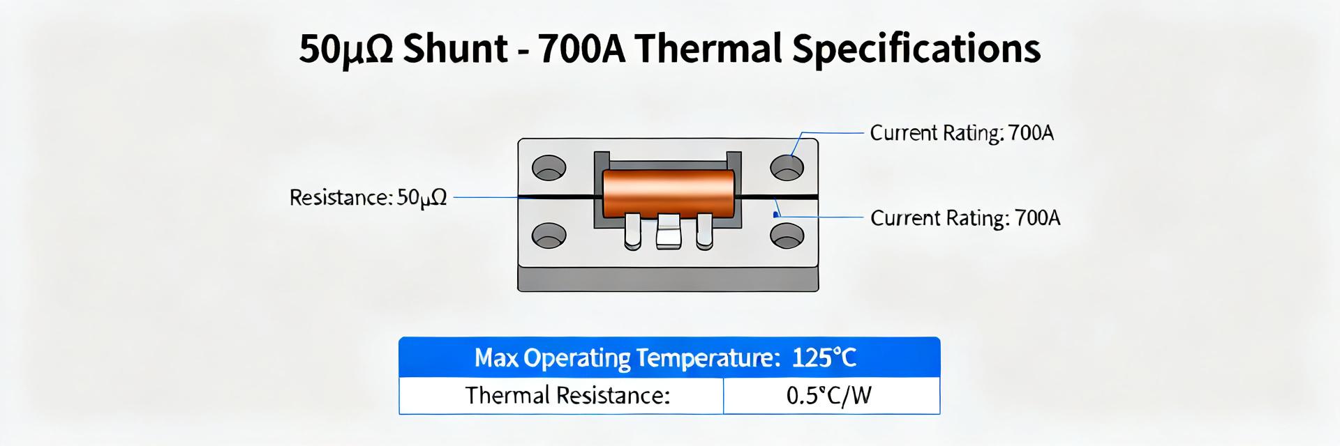
Point: Thermal characterization sets continuous and pulsed power limits and derating with ambient. Evidence: determine RθJA using steady-state powering and thermal imaging or embedded thermocouples on shunt body; derive power vs ambient derating curve showing reduced allowable power above 40–60°C. Explanation: publish Rθ values, a derating graph and recommended mounting/heat-sinking practices to keep junction/metal temperatures within limits.
Long-term stability, mechanical stress and failure modes
Point: Accelerated tests reveal common failure mechanisms and acceptable drift. Evidence: recommended protocols include thermal cycling (−40 to 125°C), humidity soak, vibration and solderability checks; acceptance might be <0.5% resistance change after specified cycles. Explanation: document expected failure modes (solder joint cracking, corrosion, slow resistance drift) and include inspection checkpoints and MTBF commentary for system risk assessment.
Bench test & measurement guide — how to reproduce datasheet numbers (method/guide)
Recommended test setup and best practices
Point: Reproducible measurement requires a controlled four-wire setup and thermal management. Evidence: use Kelvin connections, low-thermal-EMF connectors, stable current source with <0.01% stability and differential nanovolt meter; control ambient or use a windless enclosure. Explanation: step-by-step: secure shunt with specified torque, connect Kelvin leads, apply stepped DC currents, record V once thermal steady-state is reached for each point.
Data acquisition, filtering and reporting format
Point: Consistent data handling reduces noise and reporting ambiguity. Evidence: suggest sample rates that capture settling (e.g., 10 Hz for steady DC), apply moving-average or low-pass filtering and report mean ± standard deviation. Explanation: supply templates for I–V tables, drift vs time plots and thermal images; archive raw CSV plus processed JSON for reproducibility and datasheet appendix inclusion.
Applications, selection checklist & practical recommendations (action)
Typical application scenarios and sizing guidance
Point: Map the shunt to system types and ADC requirements. Evidence: battery monitoring and EV modules typically use 50–200 A ranges where a 50µΩ shunt yields 2.5–10 mV signals; power supplies and industrial drives often operate in similar bands. Explanation: recommend ADC front-ends with gain and common‑mode handling appropriate for small-millivolt signals and suggest headroom for transient currents.
Selection checklist, layout tips and alternatives
Point: A concise buying and layout checklist prevents integration errors. Evidence: checklist items: confirm max continuous current, thermal plan, accuracy target, mechanical fit and procurement tolerance. Explanation: layout tips include dedicated Kelvin traces, short low-impedance return path, thermal vias and isolation from noisy power traces; consider Hall-effect or higher-R shunts when isolation or larger Vdrop is required.
Summary
Point: The HoFL3-8436-B delivers precise low‑ohm current sensing at millivolt scale and predictable thermal behavior; this datasheet and test guidance allow engineers to validate performance. Evidence: presented nominal outputs, characterization methods, thermal derating and bench procedures. Explanation: follow the recommended tests and checklist to confirm device suitability and integrate with ADCs and thermal management for reliable system operation.
- Nominal behavior: 50µΩ shunt resistor produces 5.0 mV at 100 A, enabling high‑accuracy measurement when paired with proper ADC gain and Kelvin connections.
- Thermal & reliability: derive Rθ and use steady-state/pulse testing to produce derating curves; expect derating above typical ambient thresholds and plan heat sinking.
- Measurement practice: four‑wire Kelvin setup, low‑EMF connectors, and an uncertainty budget are required to reproduce datasheet accuracy and to document acceptance criteria.
Frequently Asked Questions
What is the typical Vdrop and power dissipation of the HoFL3-8436-B at 100 A?
Answer: At 100 A the nominal Vdrop is 5.0 mV and dissipated power is 0.5 W. These figures define sensing scale and thermal load; validate with steady‑state measurements and include derating if the ambient temperature or mounting reduces allowable dissipation.
How should I measure resistance and linearity for a 50µΩ shunt resistor?
Answer: Use a four‑wire Kelvin method with a stable current source and nanovolt‑resolution voltmeter. Sweep currents up to rated value, allow thermal equilibrium at each step, and report V vs I with linearity deviation and an uncertainty budget to support accuracy claims.
What layout and mechanical considerations ensure reliable long‑term performance?
Answer: Torque terminals to spec, keep Kelvin sense leads short, provide a robust low-impedance return and thermal path, and include thermal vias if mounted to PCB. Follow accelerated stress tests for qualification and inspect solder joints periodically for fatigue or corrosion.
How does temperature coefficient (TCR) and thermal EMF affect accuracy?
Answer: The typical TCR of 50–150 ppm/°C and thermal EMF of <1 µV/°C minimize drift and offset. Ensure measurement setups use low-thermal-EMF connections and implement firmware compensation to handle self-heating variations.