HoFL3-6918 50µΩ Shunt Datasheet: Precise Specs & Limits
High-current sensing often requires sub-milliohm accuracy and predictable thermal behavior; a 50µΩ nominal shunt class addresses that need by delivering millivolt-range drops at hundreds of amps. Engineers reading a HoFL3-6918 datasheet expect clear values for resistance tolerance, TCR, rated and peak currents, and power derating so they can size amplifiers and thermal management correctly. This article unpacks the HoFL3-6918 electrical, thermal, mechanical specs and practical limits, with worked examples, measurement checkpoints, and application guidance targeted to US design teams working on battery management and power distribution systems.
Product overview & typical use cases (background)
What the HoFL3-6918 is and key identifiers
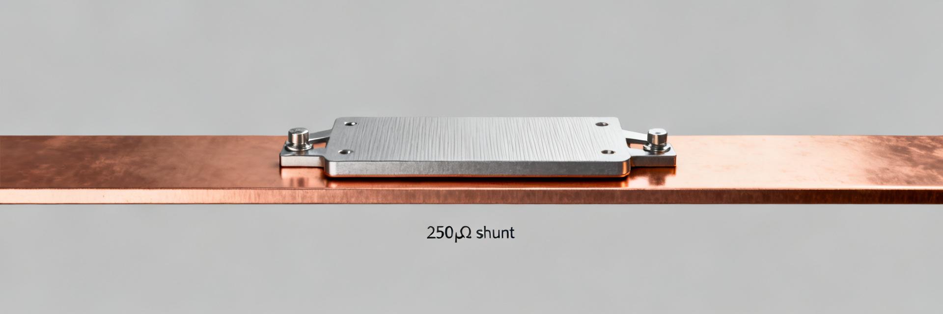
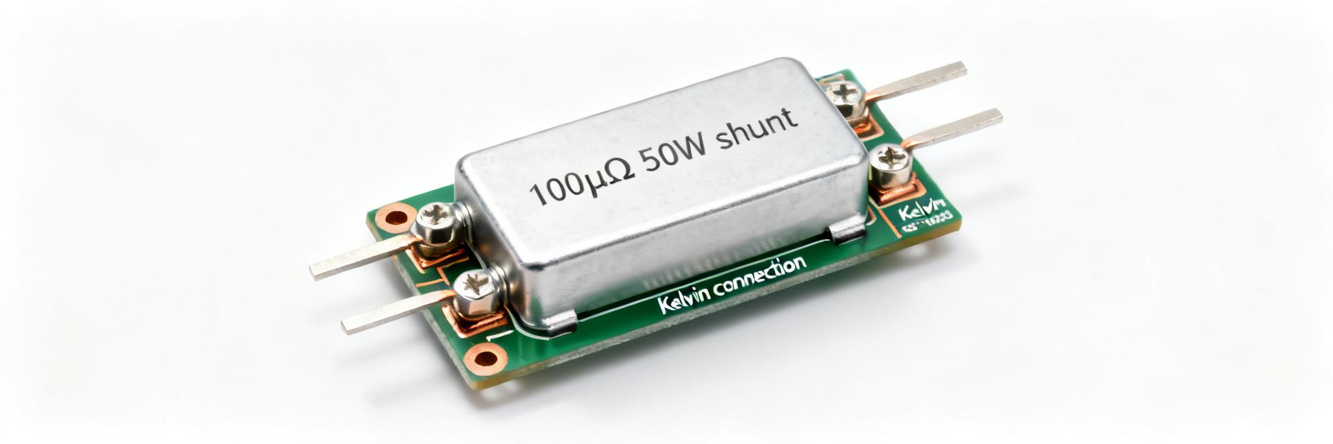
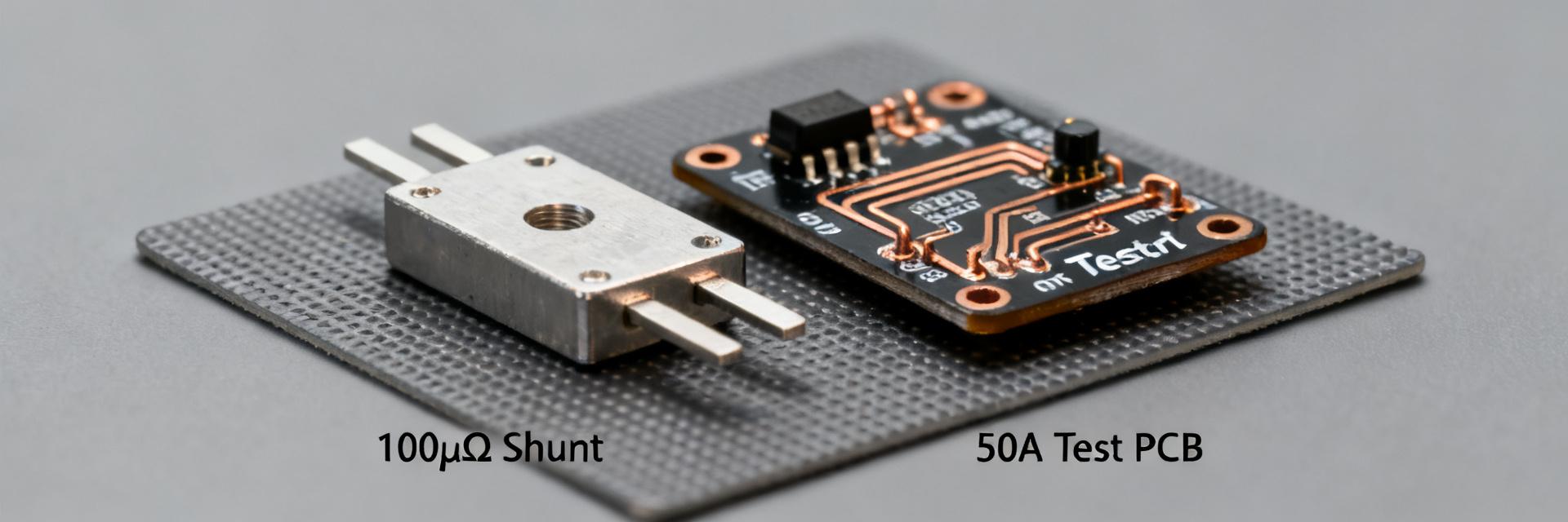
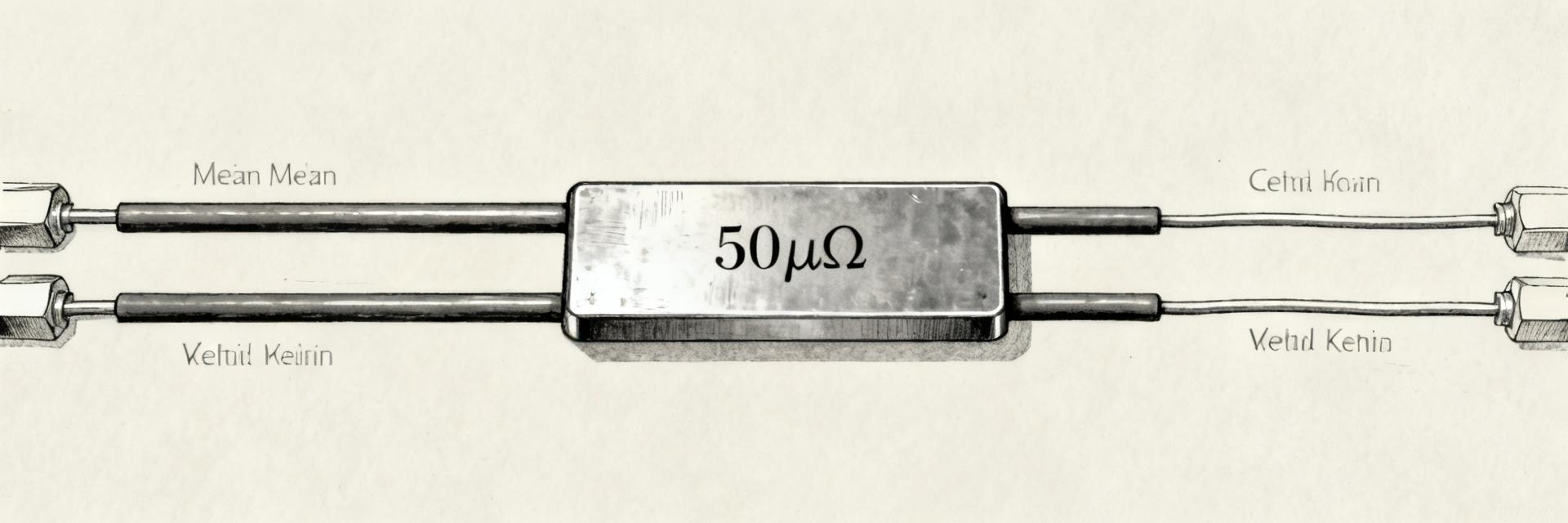
Point: The device is a four-terminal, low-value shunt intended for high-current measurement. Evidence: The nominal resistance is 50µΩ with common tolerance classes around ±1% or ±0.5% in higher-grade parts. Explanation: A four-terminal layout separates current and sense paths, minimizing contact and lead resistance influence; the part designation signals geometry and resistance so designers can match PCB or busbar mounting and select the correct tolerance class for system accuracy.
Typical applications and system-level tradeoffs
Point: Typical uses include BMS, EV/HEV gauge circuits, power converters, and high-current bus monitoring. Evidence: In these systems designers balance voltage-drop, power loss, and amplifier dynamics. Explanation: At 700 A a 50µΩ shunt produces ~35 mV and dissipates ~25 W; that voltage is easily amplified for a 12–16-bit ADC with a low-noise amplifier, but thermal rise and derating force tradeoffs between measurement accuracy and system efficiency.
Electrical specifications — resistance, tolerance, and accuracy (data analysis)
| Parameter | Specification Value | Unit | Conditions / Notes |
|---|---|---|---|
| Nominal Resistance | 50 | µΩ | At 25°C baseline temperature |
| Tolerance Options | ±0.5% / ±1.0% | % | Grade-dependent selectable classes |
| Temperature Coefficient (TCR) | ±50 | ppm/°C | Over range -55°C to +125°C |
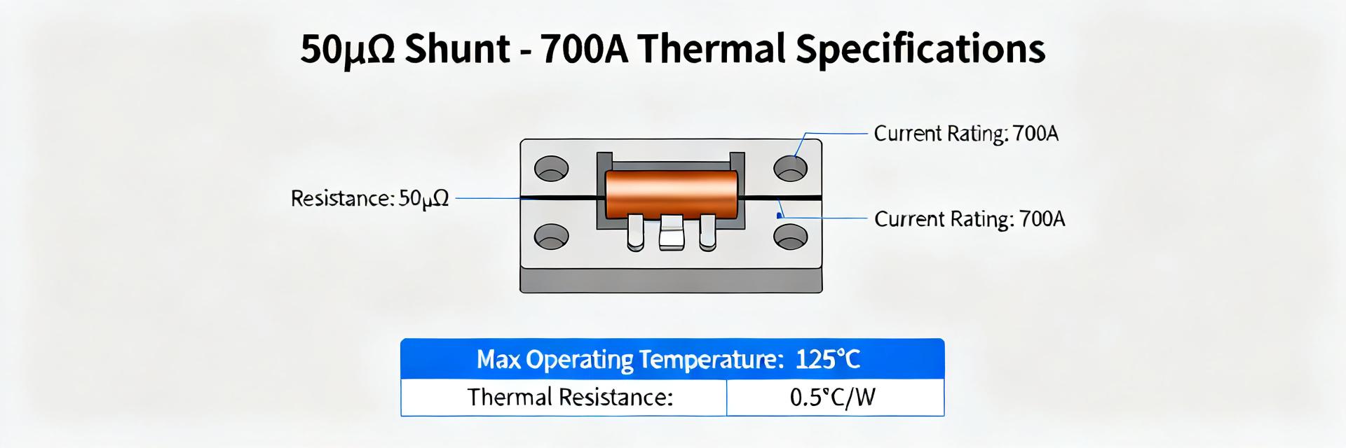
| Continuous Current Rating | 700 | A | With recommended thermal management |
| Continuous Power Dissipation | 25 | W | Derated linearly above 70°C |
Nominal resistance, tolerance classes, and temperature coefficient
Point: Nominal 50µΩ and tolerance determine base measurement error; TCR sets temperature-dependent drift. Evidence: Typical tolerance options are ±1% and ±0.5%, while a representative TCR might be 50 ppm/°C for metal-alloy shunts. Explanation and example: For a ±100°C swing a 50 ppm/°C TCR yields 5,000 ppm change (0.5%), so ΔR = 0.5% of 50µΩ = 0.25µΩ. At 700 A that ΔR produces a 0.175 mV change, which must be budgeted into total measurement error and compensated in system calibration.
Rated current, voltage drop, and measurement accuracy implications
Point: Rated continuous and peak currents define voltage drop and thermal budget. Evidence: A 700 A continuous rating gives V = I·R = 700 A·50µΩ = 35 mV and P = I^2·R ≈ 24.5 W. Explanation: For ADC integration, 35 mV can be amplified to full-scale with gain ≈90–100 for a 3.3 V ADC. Example: a 16-bit ADC with 3.3 V ref has 50.3 µV/LSB; amplifying 35 mV by 95 yields 3.325 V ≈ full scale. Designers must choose amplifier noise and CMRR accordingly to preserve SNR and avoid clipping under short-term peaks.
Thermal behavior & power limits (data analysis)
Power rating, derating curve, and thermal resistance
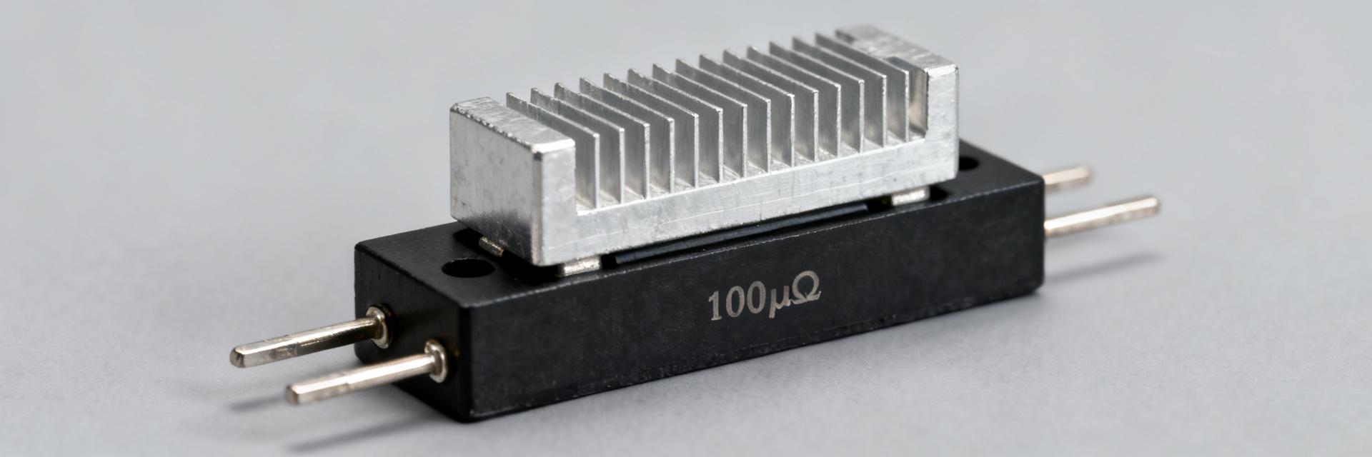
Point: The datasheet defines power rating under specified mounting and ambient conditions and provides a derating curve with temperature. Evidence: A typical 25 W continuous rating assumes a defined heat-sink or busbar thermal path; derating often reduces allowable power above a threshold ambient. Explanation: Thermal resistance from shunt body to ambient controls temperature rise; using θJA-style reasoning, ΔT = P·θ. For a 25 W case and θ≈2.5 °C/W, thermal rise ≈62.5 °C, requiring mounting or airflow to keep junctions in spec.
Overload, pulse capability, and long-term stability
Point: Short-term pulses exceed continuous ratings but stress stability. Evidence: Datasheets usually list 10 s or 1 s pulse ratings and thermal shock endurance cycles. Explanation: Repeated high-current pulses cause resistance drift via creep and microstructural changes; qualification should include pulse cycling and resistance tracking. Designers should limit duty cycle and perform life tests to quantify ppm/1000 h drift for system reliability.
Mechanical, reliability & environmental limits (method/case)
Mechanical dimensions, mounting, and connection best practices
Point: Mechanical layout and terminal treatment affect resistance and inductance. Evidence: Key dimensions include hole spacing for busbar mounting and sense-pin separation; recommended torque or soldering method is usually specified. Explanation: Use Kelvin four‑terminal mounting with short, symmetrical current paths and isolated sense pins. For PCB versions, place sense traces close to the shunt sense pins and avoid routing current return near sense lines to minimize added series resistance and inductive pickup.
Environmental ratings and lifecycle expectations
Point: Operating/storage temperatures and shock/vibration classes define suitability for harsh systems. Evidence: Typical operating ranges span wide negative to elevated temps and include shock/vibration qualification such as MIL-style or IEC test levels. Explanation: Common failure modes are mechanical fatigue, corrosion, and thermal cycling-induced drift; mitigation includes corrosion-resistant finishes, controlled torque, and thermal anchoring to reduce cyclic stress.
Measurement, test methods & application guidelines (method/guideline)
How to read the shunt datasheet: test conditions to verify
Point: Critical datasheet rows are test conditions for resistance, TCR, power rating and derating. Evidence: Look for stated measurement current, ambient, mounting method and TCR measurement method (e.g., reference temp and slope). Explanation: Verify that the specified measurement current matches your intended operating point and that derating applies to your mounting. Use the datasheet test current to compare declared resistance and ensure tolerance and stability meet system error budgets.
Practical test setups, calibration & signal-conditioning tips
Point: Proper measurement setup preserves accuracy and repeatability. Evidence: Recommended practices include Kelvin four‑wire connections, local sense amplifier near the shunt, guarding and wiring compensation. Explanation: Calibrate by measuring zero-offset with shorted input and perform temperature compensation using TCR or a lookup table. For a 50µΩ shunt, amplify the millivolt signal with a low-drift instrumentation amplifier, set bandwidth to reject switching noise, and implement periodic drift checks in firmware.
Selection checklist, comparisons & integration tips (action-oriented)
Quick selection checklist for engineers
Point: A compact decision list speeds suitability checks. Evidence: Required items include desired accuracy, continuous/peak currents, power dissipation and derating, thermal path, mounting constraints, TCR and long-term stability. Explanation: When searching vendors or comparison data use long-tail phrases like "50µΩ shunt resistor 700A 25W datasheet" or "low TCR 50 microohm shunt for BMS" to narrow results and verify that mechanical and thermal assumptions match your system.
Common pitfalls and mitigation strategies
Point: Avoid predictable integration errors. Evidence: Mistakes include ignoring TCR, underestimating thermal derating, and poor sense wiring. Explanation: Fixes are specific: adopt Kelvin sensing, add thermal vias or heat sinking, select tighter tolerance or lower‑TCR alloy, and validate with pulse cycling tests. If measured offset exceeds drift budget, rerun thermal mapping and adjust amplifier gain or add compensation in software.
Summary & key takeaways
- The HoFL3-6918 class (example token HoFL3-6918-B-50uR-1%) provides 50µΩ nominal resistance suitable for high-current sensing with millivolt‑level signals; check tolerance and TCR early to set error budgets.
- At 700 A expect ~35 mV drop and ~25 W dissipation—confirm derating curve, thermal resistance path, and required cooling; factor TCR-driven drift into accuracy calculations and calibration.
- Measurement best practices—Kelvin four‑wire, local low‑drift amplifier, and temperature compensation—are essential; use datasheet test-condition rows as a verification checklist before integration.
FAQ
How does the HoFL3-6918 affect amplifier selection for a 16-bit ADC?
Choose an amplifier that converts the nominal millivolt shunt voltage into the ADC range without exceeding common-mode limits. For example, a 35 mV source amplified by ~95 reaches 3.3 V full-scale on a 16-bit ADC (≈50 µV/LSB). Select low-noise, low-drift instrumentation amplifiers with adequate CMRR and bandwidth to preserve SNR and to reject switching noise from the power system.
What TCR should I budget for when using a 50µΩ shunt resistor in a BMS?
Budget TCR-driven drift explicitly: a representative TCR of 50 ppm/°C produces 0.5% change over a 100°C swing (0.25µΩ on 50µΩ), yielding ~0.175 mV at 700 A. Use tighter‑TCR alloys if that error is unacceptable, or implement temperature compensation and periodic calibration to keep measurement error within system requirements.
Which test conditions in a shunt datasheet are most important to verify?
Prioritize the measurement current used for resistance spec, stated TCR method and range, continuous and pulse power ratings, and the derating curve tied to mounting conditions. Confirm ambient and mounting assumptions match your design; if not, request or derive corrected derating values through thermal modeling or prototype testing.
Why is a four-terminal Kelvin connection required for the HoFL3-6918?
A four-terminal Kelvin connection separates the high-current path from the voltage sensing path. This eliminates measurement errors caused by the contact resistance of the terminals and lead wires, which can otherwise exceed the 50µΩ nominal resistance of the shunt itself.