250µΩ shunt resistor HoFL3-8518-B: Complete Datasheet
The 250µΩ shunt resistor is a low-ohm, high-current device typically specified for power ratings in the ~25 W range, with expected voltage drops such as 50 A → 12.5 mV and 100 A → 25 mV, and TCR commonly in the 50–150 ppm/°C band. This article provides a compact, specification-driven datasheet-style reference for the HoFL3-8518-B 250µΩ shunt resistor and shows engineers how to evaluate, test, and apply it in high-current sensing systems. The term datasheet is used to emphasize measurement conditions and required verifications.
Information below is organized for quick engineering use: part snapshot, electrical core specs with calculation examples, thermal/mechanical guidance, measurement and validation procedures, integration examples, and a purchasing checklist to reduce integration risk.
Product overview & primary use cases

Part ID & short spec snapshot
Part: HoFL3-8518-B. Nominal resistance: 250 µΩ. Typical nominal power rating: ~25 W (reference condition). Typical tolerance options: 0.5% and 1%. Package / mount form: busbar/metal strip style intended for bolt-on or soldered bus connections. Verify exact supplier ordering codes and footprint dimensions on the official mechanical drawing before PCB or fixture design; the compact spec table below should be populated from the vendor drawing for production release.
Typical applications & target markets
Primary applications include battery current sensing for BMS, power converters, motor controllers, high-current measurement fixtures, and charge/discharge test stands. Expected continuous current ranges commonly span tens to several hundreds of amps; low-ohm precision shunts allow low insertion loss while providing millivolt-level sense signals suitable for amplifiers and ADC front ends in automotive, energy storage, and industrial power electronics markets.
Electrical specifications (datasheet core)
Resistance, tolerance & voltage-drop calculations
Nominal resistance: 250 µΩ. Typical tolerance options: ±0.5% and ±1%. Use V = I × R to compute sense voltages. Examples: 50 A → 12.5 mV; 100 A → 25.0 mV; 200 A → 50.0 mV. These voltage levels determine amplifier gain and ADC range; design for full-scale shunt voltages typically in the 50–100 mV window for best noise and resolution trade-offs.
| Current (A) | Shunt V (mV) | Power (W) |
|---|---|---|
| 50 | 12.5 | 0.625 |
| 100 | 25.0 | 2.50 |
| 200 | 50.0 | 10.0 |
| 400 | 100.0 | 40.0 |
Power rating, derating & long-term stability (TCR, drift)
Rated power: ~25 W at specified ambient and mounting conditions; full-power capability depends on mounting and airflow. Manufacturers show a power-derating curve vs. ambient temperature—plan for linear derating above a specified temperature and compute allowable continuous current accordingly. Typical TCR ranges from 50 to 150 ppm/°C; long-term drift after hours of operation is typically low but should be validated per lot and application (expect ppm to fraction-percent scale changes over 1000-hour aging).
Thermal & mechanical characteristics
Thermal behavior: Rth, mounting impact, and thermal cycles
Thermal resistance (Rθ) from element to ambient determines temperature rise: ΔT = P × Rθ. Mounting to a large copper busbar or heatsink substantially lowers Rθ and increases allowable continuous power. Reported derating curves assume specific mounting; reproduce the vendor thermal-cycle test (recommended: multiple cycles between low and high operating temperatures) to verify mechanical stability and resistance shift under realistic conditions.
Physical dimensions, mounting & material notes
Mechanical data required: overall strip dimensions, hole/tap sizes, recommended bolt torque, and recommended soldering or welding practice. Typical busbar shunts use bolted terminals with defined torque to control contact resistance; specify bolt size and torque in the assembly drawing. Include vibration and shock test protocols in qualification to confirm ruggedness in the target environment.
Measurement, testing & verification procedures
Accurate low-ohm measurement methods
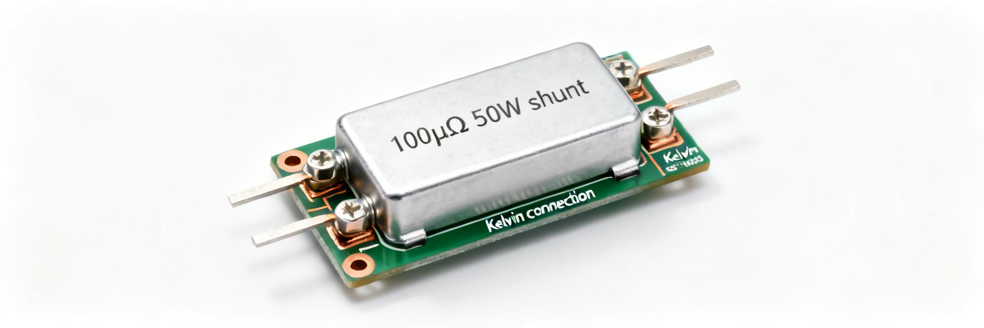
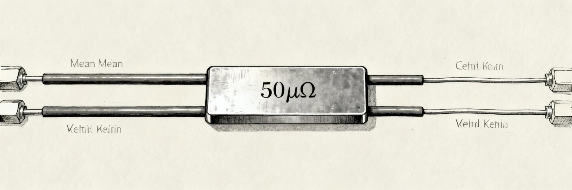
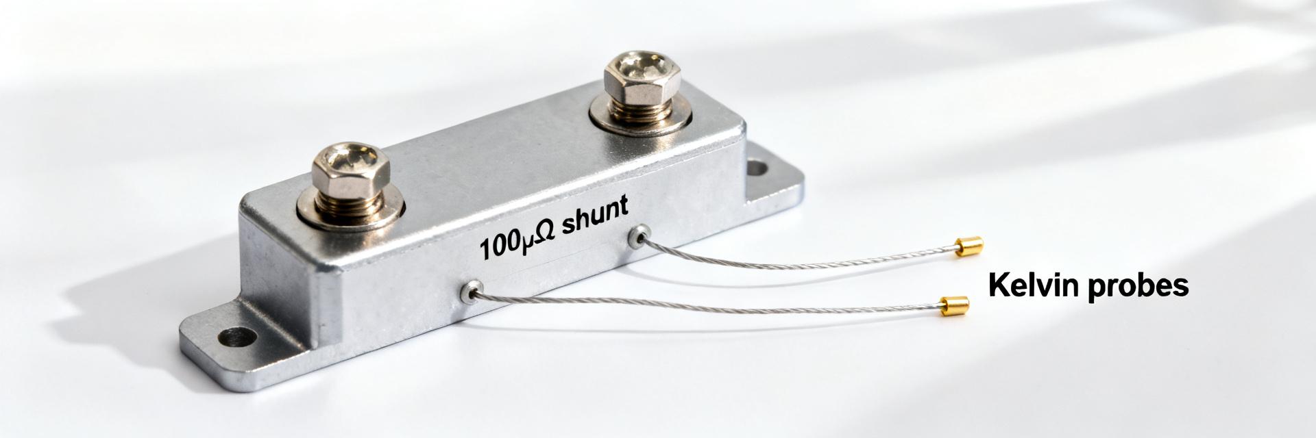
Use a Kelvin (4-wire) method: force current through the outer terminals and sense voltage on inner leads. Select a test current that yields a measurable voltage (10–100 mV preferred); for example, 40 A generates 10 mV on 250 µΩ. Use instruments with low burden and high common-mode rejection; minimize lead lengths and avoid thermoelectric junctions. Record ambient and fixture temperatures for TCR calculations.
Validation tests to reproduce datasheet claims
Bench tests: resistance verification at room temperature, power dissipation test ramping current to rated power while monitoring thermal rise, TCR measurement across the specified temperature range, thermal imaging to locate hot spots, and long-term stability testing (e.g., 1000-hour soak at elevated temperature and power). Document test currents, measurement uncertainty, and fixture details in the test report.
Installation, integration & example circuits
Mounting options and electrical integration
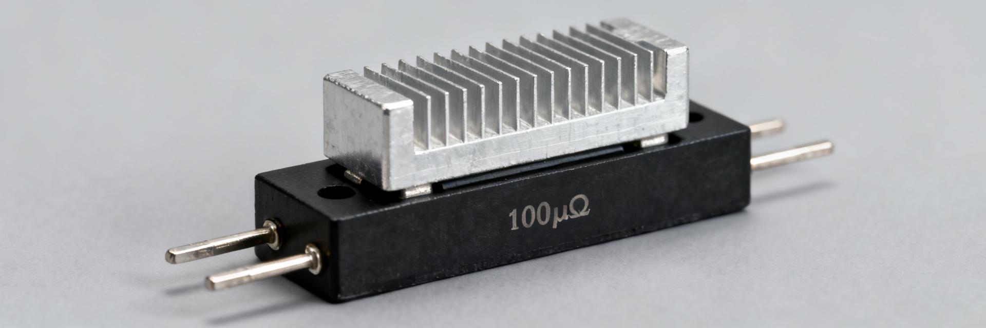
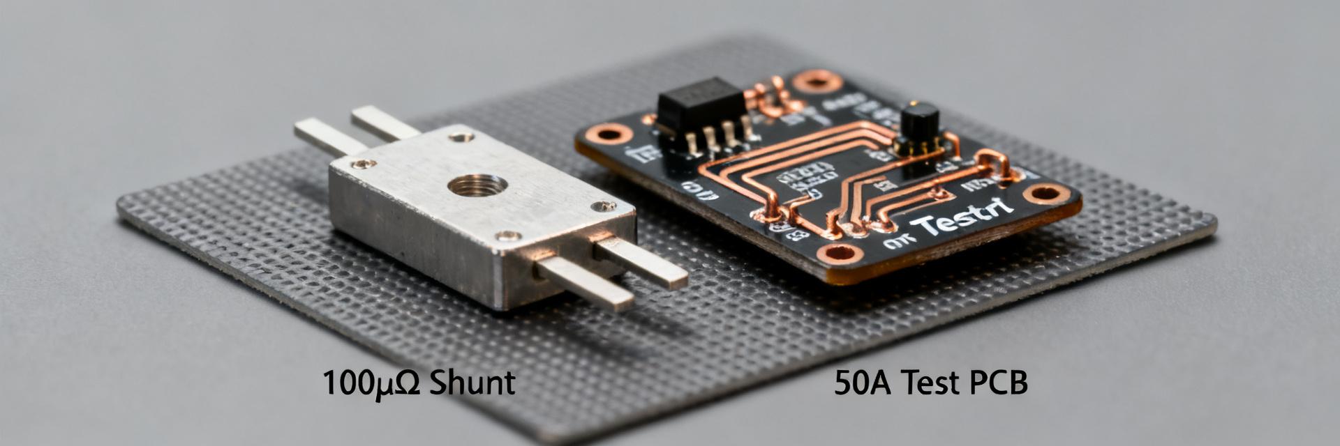
Compare busbar (best thermal path), bolt-on (mechanical simplicity), and PCB-mounted (limited current) options. Size conductors for continuous current and peak transients; place sense leads close to the shunt body to avoid parasitic drops. Do: use insulated washers where needed, apply correct torque, and provide strain relief. Don’t: route high-current return paths through measurement sense traces.
Example application circuits and design targets
Example 1: Battery current-sense front-end—target full-scale shunt voltage 50–100 mV. With 250 µΩ, 50 mV corresponds to 200 A; choose amplifier gain = Vadc_fs / Vshunt_max and filter to limit bandwidth. Example 2: High-current measurement—use instrumentation amplifier with differential filtering and common-mode rejection; calculate ADC LSB in amps = (Vref / ADC_counts) / (Gain × Rshunt) and design gain to utilize ADC range without saturating on transients.
Purchasing, compliance & datasheet checklist (actionable)
What to check on supplier datasheets before purchase
Checklist: nominal resistance & tolerance; rated power and derating curve with mounting conditions; TCR value and test temperature range; measurement method/conditions and calibration tolerance; full mechanical drawing with hole sizes and torque specs; recommended solder/weld practice; lot traceability and qualification test reports.
Handling, storage & reliability considerations
Handling: avoid mechanical bending or point loads on strip body; protect terminals from contamination and oxidation. Store in clean, dry conditions per vendor recommendations. Incoming inspection: verify resistance at defined current, inspect mechanical dimensions, and perform a sample thermal run-in for critical production lots.
Summary
The HoFL3-8518-B 250µΩ shunt resistor is designed for precision, high-current sensing where millivolt-level signals are amplified for measurement or control. Use the datasheet parameters—resistance, tolerance, rated power, TCR, and mechanical drawing—to validate electrical, thermal, and mechanical suitability. For production, confirm derating under your mounting conditions and run the outlined validation tests to reproduce datasheet claims.
Key summary
- Nominal 250µΩ resistance with ±0.5%/±1% tolerance: calculate V = I×R for amplifier/ADC sizing and verify with Kelvin measurement procedures before integration.
- Rated power ~25 W referenced to specific mounting conditions: reproduce the vendor derating curve for your busbar or heatsink configuration to set continuous current limits.
- TCR ~50–150 ppm/°C and low long-term drift expected: include TCR testing across temperature and 1000-hour stability checks for critical designs.
Frequently Asked Questions
How do I measure a 250µΩ shunt resistor accurately?
Use a Kelvin 4-wire method with a test current chosen to produce 10–100 mV across the shunt (for example, ~40 A yields 10 mV). Keep sense leads short, avoid thermoelectric junctions, record ambient temperature, and use instrumentation with low input offset and high common-mode rejection to achieve ppm-level accuracy.
What power rating and derating should I expect for a 250µΩ shunt resistor?
Expect a nominal rated power near 25 W under specific mounting conditions; allowable power falls with increasing ambient temperature per the vendor derating curve. Always verify the derating curve for your mounting method (busbar, bolt-on, or PCB) and include safety margin for transient heating.
Is the 250µΩ shunt resistor suitable for battery management systems?
Yes. Its low resistance yields low insertion loss while providing millivolt-level signals suitable for BMS amplifiers and ADCs. Verify that the full-scale shunt voltage at expected currents matches amplifier and ADC ranges, and qualify TCR and long-term stability for the battery temperature profile.
What mounting methods are recommended for the HoFL3-8518-B shunt resistor?
The recommended mounting options include direct copper busbar mounting for optimal thermal pathways, heavy-duty bolt-on connections with specified assembly torque, and high-copper-weight PCB integration for lower continuous current ranges. Keep trace paths short to avoid noise injection.