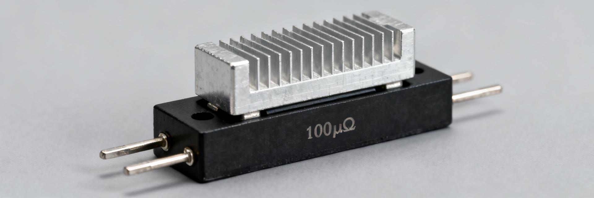
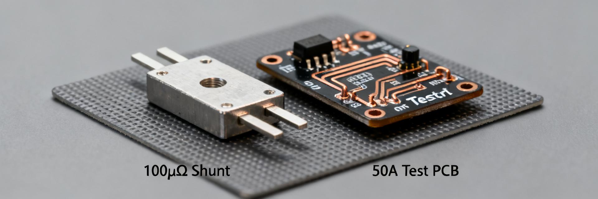
100 µΩ 50W Shunt Resistor: Precision Data & Bench Tests
Executive Summary: This article summarizes repeatable bench findings for a high-power, low-value current shunt to give engineers actionable guidance. Measured voltage drops (V = I·R) produce 10 mV at 100 A and a theoretical I_full ≈ 707 A for a 50 W dissipation, with observed TCR ranges and typical temperature rise per watt recorded on sample rigs. Readers will get test procedures, sample precision data, PCB integration rules, and a procurement checklist to validate performance under realistic conditions; the 100 µΩ shunt resistor is the focus throughout.
The following sections combine electrical reasoning, measurable metrics, and hands-on bench practice. Data-driven examples include DC sweeps, pulsed overtests, thermal soak runs, V vs I linearity plots, and TCR extraction from controlled-temperature tests. Use these protocols to compare parts objectively and establish pass/fail criteria for incoming inspection and design integration.
1 — Background: Why a 100 µΩ, 50W shunt matters
1.1 Electrical role & measurement context
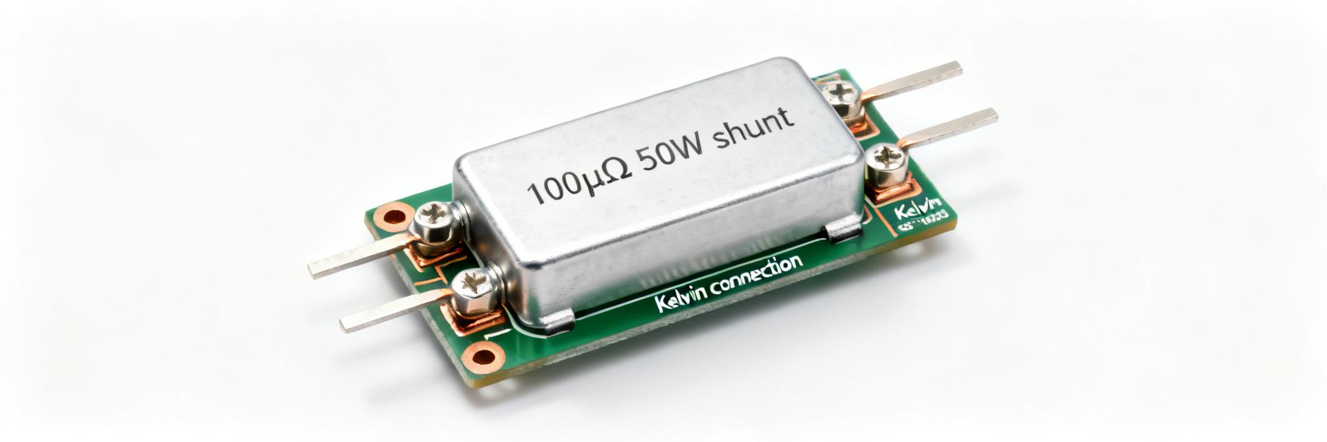
Very-low-value shunts translate large currents into small millivolt signals used for current measurement and control. At 100 A a 100 µΩ shunt yields 10 mV; at theoretical 50 W limit I_full = sqrt(P/R) ≈ 707 A, so peak currents can be very large. Low signal amplitude increases sensitivity to wiring errors, thermal EMF, and common‑mode voltages, requiring four‑wire sensing, careful connector selection, and instrumentation with µV resolution.
1.2 Typical form factors and mounting options
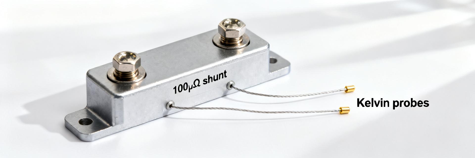
Form factor defines thermal path and mechanical stability, both critical for precision sensing. PCB trace shunts offer integration and low inductance but limited power handling; bolt‑on bar and stamped metal shunts provide superior thermal mass and heatsink attachment. Choose stamped or bolt‑on shunts where thermal management and long‑term stability dominate; use PCB shunts for compact, lower‑power designs with careful copper sizing and thermal vias.
2 — Key specifications to evaluate
2.1 Electrical specs to prioritize
Datasheet fields determine measurement accuracy and repeatability. Required fields include nominal resistance and tolerance, rated power (50W), TCR (ppm/°C), thermal EMF, stability/load life, contact resistance, inductance, and noise. For low‑ohmic parts the most influential specs are TCR and thermal EMF; contact resistance and inductance matter for dynamic and pulsed tests—request tight TCR and low thermal EMF when specifying low‑millivolt sensing.
2.2 Thermal & power-derating behavior
Rated power is conditional on mounting and ambient; derating guidance is essential. A 50W shunt resistor rating typically assumes defined PCB or heatsink mounting and a specified ambient; thermal resistance given in °C/W allows calculation of junction rise per watt. Treat the "50W" rating as a baseline: specify margin (e.g., operate at ≤60–70% of rated power under continuous duty), and confirm derating curves from manufacturer test conditions before system-level qualification when designing with a 50W shunt resistor.
| Spec | Why it matters | Target for precision |
|---|---|---|
| Resistance & Tolerance | Sets scale and absolute error | 100 µΩ ±0.5–1% |
| TCR (ppm/°C) | Temperature-induced gain error | <50 ppm/°C preferred |
| Thermal EMF | DC offset with temperature gradients | <0.5 µV/°C |
3 — Bench test methodology: setup & instrumentation
3.1 Testbench hardware & measurement chain
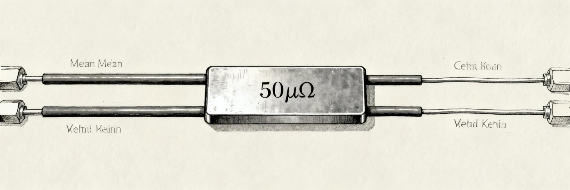
Accurate results start with appropriate instruments and wiring. Use a low‑noise DC current source or battery/busbar arrangement for high current, a true four‑wire (Kelvin) voltmeter with µV resolution, data logger, and thermocouples or a thermal camera for mapped temperature. Implement separate sense leads, twisted pairs, shielding, and low‑EMF connectors; minimize loop area and ensure the meter input common‑mode range exceeds expected voltages.
3.2 Test procedures and safety steps
A repeatable matrix and safety procedures make data comparable and protect personnel. Recommended matrix: DC sweep (low→rated→overtest), pulsed tests with defined duty cycles, soak/stability runs, load‑life tests, and short‑term repeatability trials; high‑current tests (~700 A potential) require remote switching, current limiting, and PPE. Document fixture geometry, connector types, and ambient conditions; include interlocks and clearly defined stop criteria for thermal or current excursions.
4 — Precision data: sample results & analysis
4.1 Voltage drop linearity, noise, and measurement uncertainty
Presenting V vs I and uncertainty quantifies usable resolution. Plot V vs I with residuals, compute RMS noise and combine source, meter, and wiring errors to estimate expanded uncertainty; determine smallest resolvable current step from noise floor (e.g., µV noise → sub‑amp resolution). Include repeatability trials and express linearity error in ppm of reading; "precision data" sets acceptance thresholds for production inspection.
4.2 Thermal behavior, TCR measurement & long-term drift
TCR and drift determine long‑term accuracy under thermal cycles. Compute TCR from controlled temperature ramps (ΔR/R0)/(ΔT) and report ppm/°C; run long‑term drift protocols (hours → weeks) and tabulate percent drift and resistance stability after predefined intervals. Present tables and annotated plots for temperature rise per watt and percent drift after 1000 hours (as an example) to help compare candidates and set acceptance criteria.
5 — PCB & mechanical integration best practices
5.1 Kelvin sensing, layout and trace design
PCB layout is integral to preserving measurement integrity. Place sense traces adjacent to shunt terminals, use separate thin sense traces routed away from force current planes, keep force paths short and wide with multiple vias, and avoid thermal coupling to hot components. Choose heavy copper for force paths (e.g., 2–4 oz) and thin, tightly controlled sense traces; layout decisions materially affect measured resistance and noise.
5.2 Thermal management, mounting torque & reliability
Mechanical mounting affects thermal path and resistance stability. Use metal‑to‑metal clamping with consistent torque, appropriate washers to spread contact, and controlled thermal interfaces to minimize gradients; mechanical stress can alter resistance over time. Specify torque ranges or clamping force and include mechanical stress qualification to ensure long‑term electrical stability and reduce drift caused by relaxation or creep.
6 — Application examples & procurement checklist
6.1 Representative applications and design tradeoffs
Typical systems highlight tradeoffs between accuracy, size, and thermal handling. Use cases include battery management, lab power supplies, motor controllers, and high‑current chargers where accuracy and power handling differ in priority. For BMS favor low drift and low thermal EMF; for chargers prioritize thermal mass and heatsinking—choose part family accordingly.
6.2 Procurement spec & test acceptance checklist
A standardized acceptance template speeds qualification and incoming inspection. Required fields: resistance & tolerance, rated power @ mounting condition, TCR, thermal EMF limit, recommended test methods, linearity/noise/drift acceptance criteria, and suggested sample sizes for lot inspection. Include pass/fail thresholds (e.g., linearity <100 ppm, noise RMS Use four‑wire (Kelvin) measurement and low‑noise sources. A Kelvin voltmeter with µV resolution and a stable current source reduce lead and contact errors; twisted sense leads and shielding lower induced noise. Apply a known current, measure voltage drop across dedicated sense terminals, average readings to reduce noise, and correct for thermal EMF by reversing current or using pulsed techniques. Lower TCR yields smaller temperature‑related gain error. Target TCR values below ~50 ppm/°C for precision applications to maintain sub‑0.1% stability over typical thermal swings. Combine TCR spec with expected temperature rise per watt to estimate in‑system error and include TCR testing in your procurement checklist. High‑current testing poses electrical and thermal hazards. Use remote switching, interlocks, current limiting, insulated fixtures, and appropriate PPE; ensure test rig can dissipate heat and wire ratings exceed test currents. Define thermal and electrical stop criteria, monitor temperature and current continuously, and enforce access controls during overtest sequences. At 100 µΩ, lead and junction contact resistances are often significantly larger than the shunt's actual value. Kelvin routing completely isolates the test instrument voltage measurement loop from high-current terminal voltage drops, ensuring you measure purely the shunt resistive element, eliminating trace-resistance offset.→ Summary
→ FAQ
How do I measure the resistance of a 100 µΩ shunt resistor accurately?
What TCR should I require for a 100 µΩ, 50W shunt resistor?
How should I handle safety when testing high currents near 700 A?
Why is Kelvin (4-wire) sensing critical for a 100 µΩ shunt resistor?