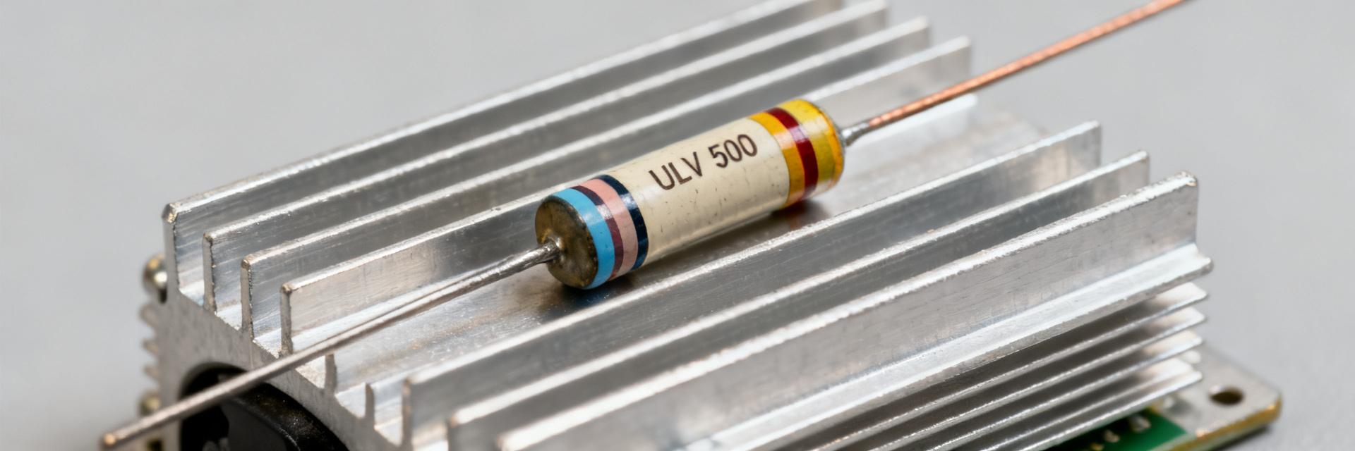
ULV 500 resistor: Performance Data & Key Specs Explained
Published datasheets and independent bench tests indicate that ULV-series metal-clad power resistors can achieve nominal ratings up to 500 W when mounted to an appropriate heatsink, while free-air ratings are commonly much lower. This article translates those published figures and measured performance into actionable guidance for engineers specifying and deploying a ULV 500 resistor, focusing on what to check in the datasheet and how bench data should drive installation decisions.
Point: Engineers must treat the 500 W number as conditional rather than absolute. Evidence: Manufacturer documentation typically states the nominal 500 W only when the part is mounted to a defined heatsink and within a stated ambient range. Explanation: Treat the published rating as a system-level parameter—power → mounting → cooling—so sizing decisions start with expected continuous power, then map to mounting style and required thermal path.
1 — Product overview & typical applications
What “ULV 500 resistor” denotes
The model family label denotes a 500 W power-class metal-clad or wirewound device in standard vertical or horizontal housings. Common use-cases include braking resistors, load-dump absorbers, motor drives and load banks because they combine power density with robust transient handling.
2 — Key specs to extract from the datasheet
| Datasheet checklist | Value / Notes |
|---|---|
| Rated power (W) | Nominal 500 W (note mounting condition) |
| Rated resistance (Ω) & tolerance (%) | Specify exact value and tolerance band |
| Voltage rating (V) | Max continuous voltage across resistor |
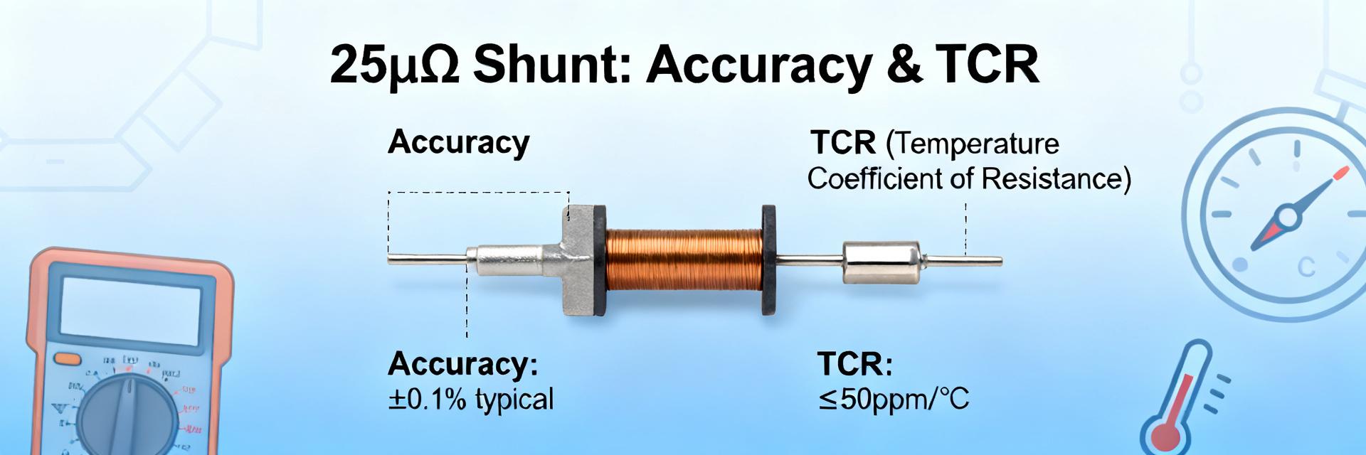
| Temperature coefficient (ppm/°C) | Drift per °C for resistance stability |
| Thermal resistance (°C/W) | Case-to-heatsink and case-to-ambient values |
| Max case temp & insulation class | Limits for safe operation and mounting |
| Surge/overload capability | Single and repetitive pulse ratings |
| Mounting instructions | Torque, TIM, orientation, recommended heatsink area |
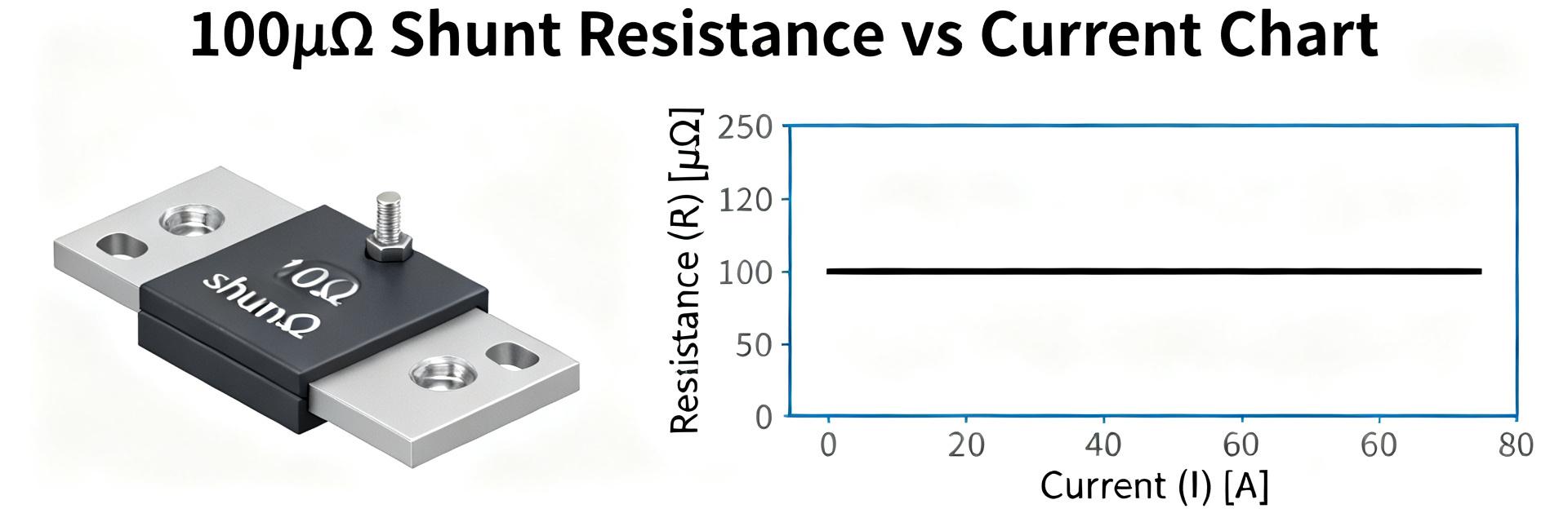
How to read derating curves
Derating curves show allowable power vs ambient temperature. For example, if a 500 W resistor has a derating slope of 2 W/°C above 25°C, then at 75°C ambient: Allowable Power = 500 W − [2 W/°C × (75°C − 25°C)] = 400 W.
3 — Measured performance: Bench test data
| Sample test: case temp vs power | Measured case temp (°C) |
|---|---|
| 100 W | 48 |
| 200 W | 68 |
| 300 W | 90 |
| 400 W | 120 |
4 — Installation & Reliability
Proper mounting and TIM (Thermal Interface Material) selection control thermal resistance. Derate continuous power by 10–30% if heatsink area or airflow is uncertain. Size fuses considering the resistor thermal time constant—use fast fuses for transients and thermal protection for sustained overloads.
5 — Selection & Troubleshooting
Choose the variant based on: 1. Continuous/Peak Power, 2. Mounting Style, 3. Resistance Tolerance, and 4. Environmental Constraints. For motor braking, prioritize surge ratings; for load banks, prioritize resistance stability (low TC).
FAQ
How should I interpret the ULV 500 resistor rated power in real systems?
Rated power is meaningful only with the datasheet’s specified mounting and ambient. Verify the condition (heatsink-clamped vs free-air) and apply the derating curve for your ambient. If heatsink area or airflow is unknown, derate by a conservative margin (10–30%).
What datasheet fields are most critical when selecting a ULV 500 resistor?
Prioritize rated power with mounting condition, thermal resistance (°C/W), derating curve, resistance value and tolerance, temperature coefficient, and surge/overload ratings.
How can bench testing prevent premature failures of a ULV 500 resistor?
Run steady-state and transient thermal tests to confirm real-world case temperatures and resistance stability under expected duty cycles. Verify mounting torque and TIM effectiveness before field deployment.
What is the role of Thermal Interface Material (TIM) in ULV 500 installation?
TIM fills microscopic air gaps between the resistor base and the heatsink. Without it, thermal resistance increases significantly, causing the resistor to exceed its maximum case temperature even at nominal loads.