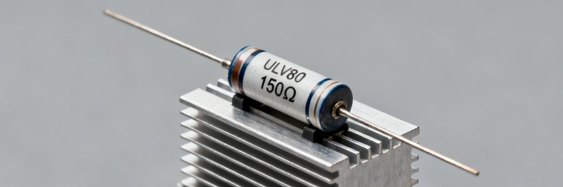
ULV80 Resistor 150Ω FL=1000: Complete Spec & Thermal Data
Thermal limits are the primary constraint for high-power metal-clad resistors: uncontrolled dissipation increases component temperature proportionally to power times thermal resistance, often causing failure before electrical limits are reached. This article provides a single-source reference for the ULV80 resistor 150Ω FL=1000 — explaining each spec field, thermal calculation methods, pulse/braking sizing workflows, and practical installation plus maintenance rules to avoid overheating and downtime.
The goal is to let design and test engineers verify datasheet claims, calculate Rth-driven temperature rise, size for continuous and transient braking loads, and document installation and monitoring steps so field failures drop markedly.
1 — Background: ULV80 series & "150Ω FL=1000" Logic
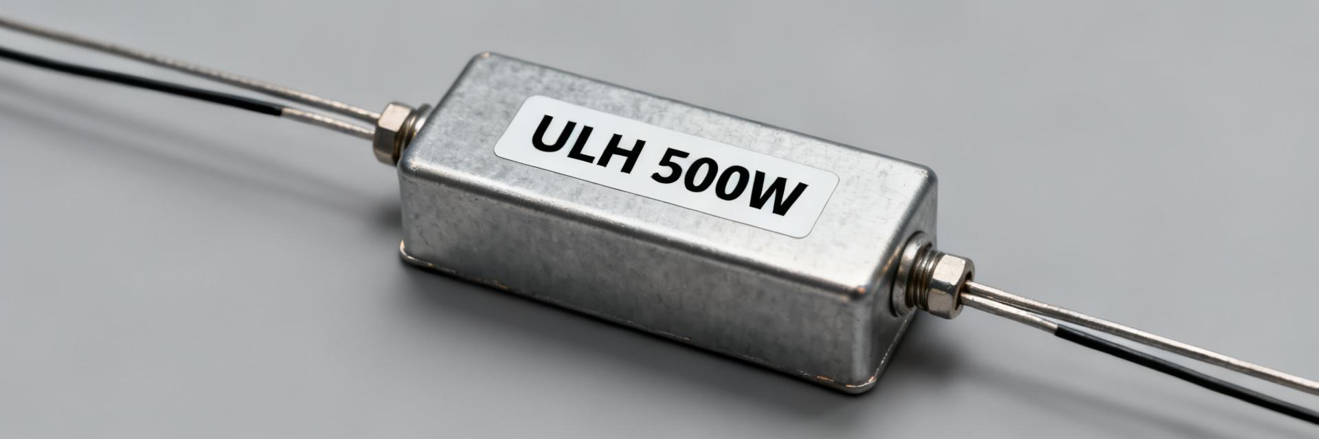
— Construction & Features
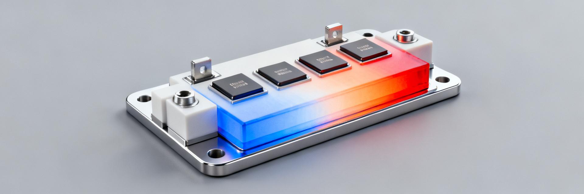
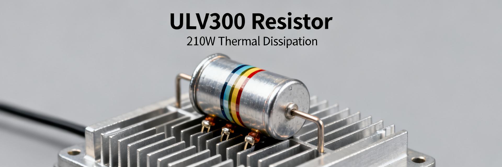
The ULV80 series consists of metal-clad, wire-wound power resistors. The metal housing provides a robust thermal path to a mounting flange, essential for high-density power applications. The material stack—ceramic substrate, alloy wire, and aluminum or stainless housing—determines both the thermal resistance (Rth) and the thermal capacitance (Cth) of the unit.
— Interpreting "150Ω" and "FL=1000"
While 150Ω is the nominal resistance, FL=1000 usually denotes Flying Leads of 1000mm. However, in industrial sourcing, this must be cross-referenced with the vendor's specific lot code or pulse rating shorthand.
| Field | Source/Verification | Declared Value |
|---|---|---|
| Resistance (Ω) | Datasheet p.1 | 150 ± 5% (Typical) |
| FL Code Meaning | Drawing/Spec | 1000mm Flying Leads |
2 — Complete Electrical Specification Fields
Capturing standardized fields ensures safety checks are unambiguous. Essential fields include resistance, tolerance, rated continuous power (W), pulse energy (J), and TCR (ppm/°C).
3 — Thermal Performance: Rth & Derating
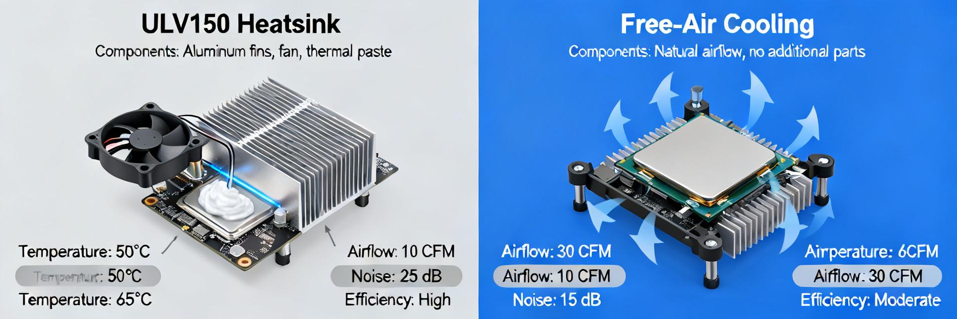
Core thermal equations convert electrical power into heat. Use ΔT = P × Rth to determine the rise above ambient. Selecting the correct Rth based on mounting (Free Air vs. Heatsink) is critical for longevity.
| Mounting Mode | Est. Rth (°C/W) | Derating Factor (at 40°C) |
|---|---|---|
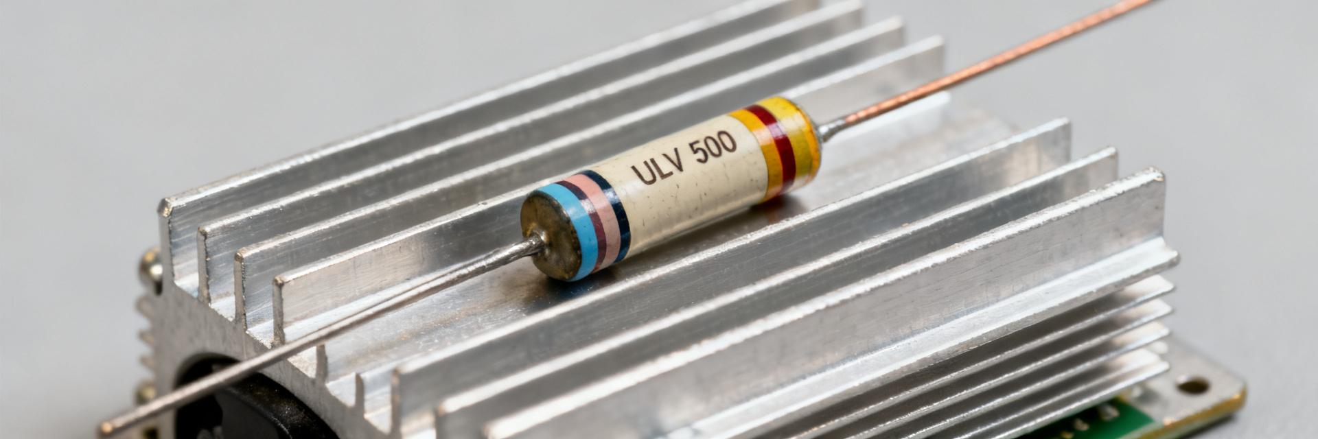
| Free air, horizontal | 2.5 - 3.2 | 0.60 |
| Flange to Heatsink | 0.8 - 1.2 | 0.90 |
4 — Sizing for Braking & Pulse Loads
For short braking pulses, compute energy E = ∫P(t) dt. Ensure the transient temperature rise ΔT_pulse ≈ E / Cth does not exceed the maximum operating temperature (Tmax). If FL=1000 includes a specific energy pulse rating, it must be validated against the duty cycle to prevent cumulative heat soak.
5 — Selection & Comparison Guidelines
| Parameter | ULV80 150Ω | Standard Wirewound |
|---|---|---|
| Housing | Metal-Clad (High Rth efficiency) | Ceramic/Silicone |
| Pulse Stability | High (Excellent Cth) | Moderate |
6 — Installation & Maintenance FAQ
What is the most common failure mode for the ULV80?
Thermal runaway due to improper heatsink contact or exceeding the pulse energy limit, leading to internal wire-wound rupture or insulation breakdown.
How should the 1000mm leads (FL=1000) be managed?
Ensure leads are properly strain-relieved and routed away from the hot resistor body to prevent insulation melting. Use high-temp sleeving if routing near the flange.
Can I use the ULV80 without a heatsink?
Yes, but you must apply significant derating (often 50% or more) as the Rth in free air is much higher than when flange-mounted.
What maintenance is required for power resistors?
Periodic IR thermography to check for hot spots and checking terminal/mounting torque to ensure consistent thermal conduction and electrical contact.
Summary
- Verify FL=1000 as 1000mm flying leads; ensure wire gauge matches current requirements.
- Calculate ΔT = P × Rth and apply a 10–25% safety margin for continuous loads.
- Use Heatsink mounting to maximize the ULV80's power density and minimize footprint.
- Implement routine IR monitoring to catch resistance drift before failure.