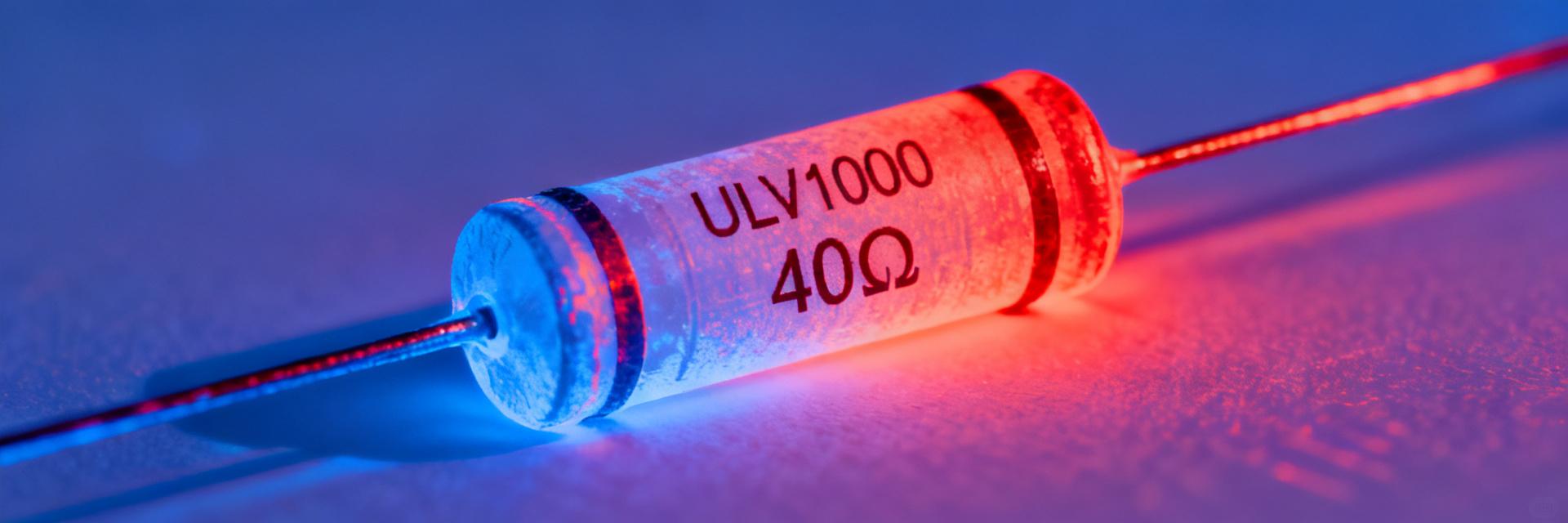
ULV1000 40 ohm braking resistor: Latest thermal data
Essential insights for reliable dynamic braking in modern drive systems.
Recent bench tests and thermal models clarify safe continuous power, temperature rise and derating for the ULV1000 braking resistor, essential for reliable dynamic braking in modern drives. This article summarizes measured thermal limits, recommended test methodology, sizing worked examples, installation best practices and a compact checklist for system integrators.
01 Introduction (data_driven hook)
Measured thermal behavior governs braking-resistor selection and enclosure design; small errors lead to overheating or unnecessary overspec. Readers will get steady-state temp rise, thermal resistance, time constants, derating examples and test templates they can run on their bench to validate ULV1000 40 ohm parts in their system.
Background: ULV1000 braking resistor — key specs & thermal relevance
Essential product specs to note
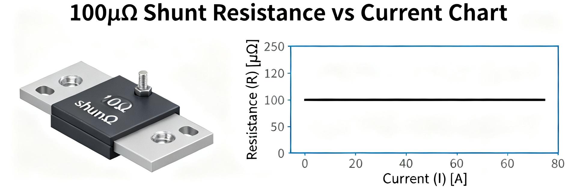
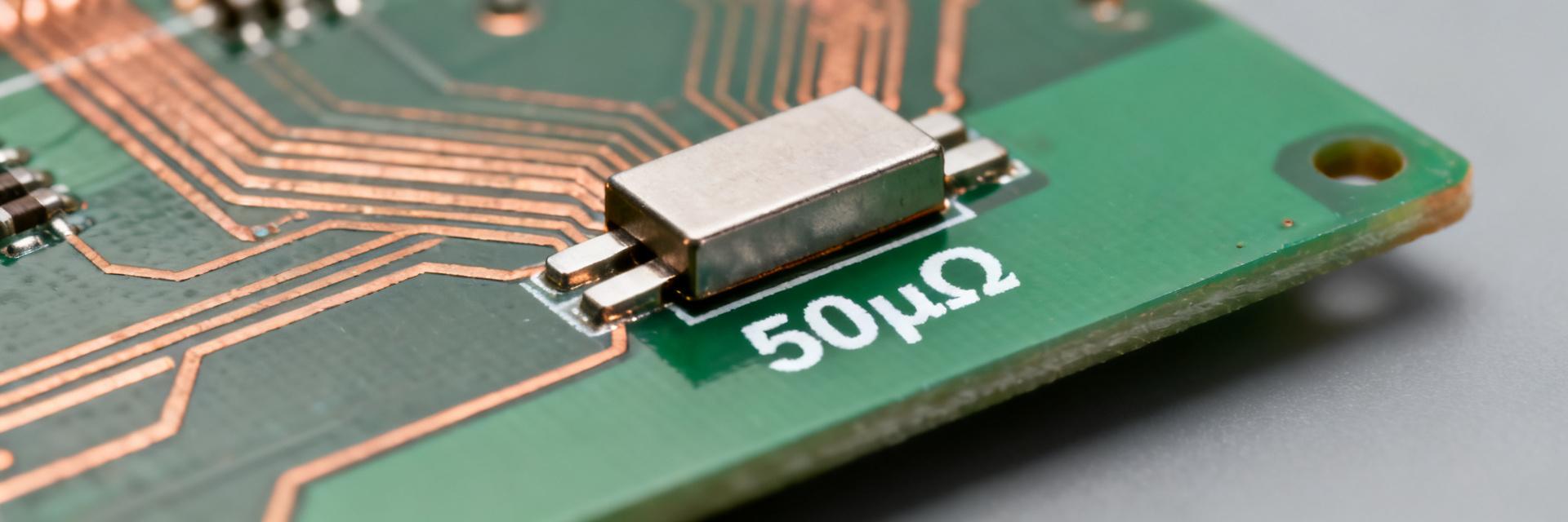
Key fields: resistance 40 ohm, nominal wattage rating (model-dependent), physical form factor (finned/aluminum case), construction materials and mounting options. Surface area, thermal mass and coating directly affect dissipation; larger area and thicker fins lower thermal resistance and slow temperature rise for identical energy input.
Why thermal data matters
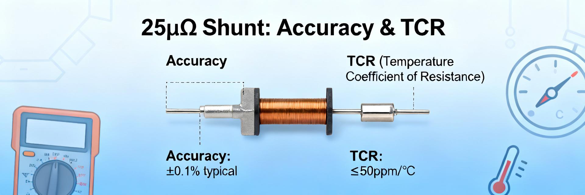
Thermal metrics define continuous versus peak braking limits, overtemperature risk and MTBF implications. Accurate derating curves and ambient limits determine warranty-safe operation and required thermal cutouts. Compliance items to check include ambient rating, enclosure class and recommended maximum surface temperatures for safety and longevity.
Latest thermal data summary — what the tests show
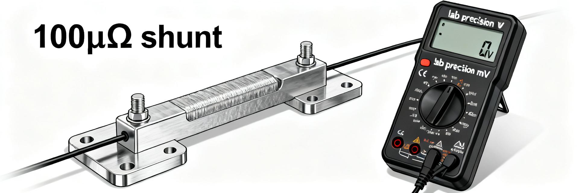
Test matrix & measurement methodology (what to report)
Recommended conditions: ambient 25°C, 40°C and 60°C; instrumentation: surface thermocouples and calibrated IR as cross-check; mounting on metal chassis vs isolated hang; airflow: natural and forced (specified CFM). Report load profiles for continuous and pulsed stops, uncertainty and repeat runs to quantify variance.
* Label unverified data explicitly for final documentation.
Headline thermal metrics to present
Report steady-state temp rise (°C), thermal resistance (°C/W), time constants (time to 63% of rise), peak surface temps for defined duty cycles and any hotspots. Include temp-vs-time and derating curves.
Thermal performance across operating conditions
Ambient temperature and derating behavior
Continuous allowable power must be derated with ambient. Use a linear approximation:
P_allowed(Ta) = P_rated * (T_max − Ta) / (T_max − T_ref)
Example: if P_rated at 25°C is 1000W and T_max is 175°C, compute reduced continuous W at Ta=40°C. Provide derating curve or table for quick lookup.
Mounting, enclosure, and airflow effects
Mounting orientation and proximity to panels matter: bolting to a large metal chassis can lower steady-state temps by 10–25% versus isolated mounts. Forced air at modest 50–200 CFM can reduce peak surface temps by ~15–40% depending on flow path; maintain minimum clearance and intake/exhaust paths in enclosures.
How to interpret ULV1000 braking resistor thermal data
Using test curves to size a resistor for a drive
- 1 Compute energy per stop: E = 0.5 · J · Δω²
- 2 Convert to heat per stop (E joules).
- 3 Use thermal capacity/time constants to find temp rise per pulse.
Ensure average power (E·stops/sec) stays below derated continuous power with margin (typically 20–30%). Insert measured Rth and τ from test data.
Thermal modelling and safety margins
Simple lumped model: ΔT = Rth · P_avg for steady state; for pulses, use ΔT_pulse = E/Cth and exponential recovery with τ = Rth·Cth. Recommend a safety margin of 20% above measured safe continuous power and monitoring with a thermistor or thermal cutout to prevent latent overheating in fielded systems.
Empirical test cases & recommended test templates
Case A — Continuous
Setup: Resistor on intended chassis, 25°C ambient, no forced air. Apply constant DC power.
Pass/Fail: Steady-state temp below rated surface limit and within derating curve.
Case B — Intermittent
Setup: Define energy per stop (e.g., 5 kJ) at 1 stop/min. Record peak temps and recovery curve.
Interpretation: Check if long-term average power meets safe limits with required margins.
Practical recommendations & selection checklist
Installation Best Practices
- Mount on a conductive chassis when possible.
- Orient fins to promote vertical convection.
- Provide minimum clearances of 25–50 mm.
- Add forced-air paths if ambient exceeds derating threshold.
- Add a thermistor or thermal cutout for active protection.
Spec & Procurement Checklist
Key Summary
- ✔ Steady-state limits: Use measured thermal resistance to compute allowable continuous power; verify with chassis-mounted tests and 20% safety margin.
- ✔ Derating rule: Reduce continuous W with ambient using a linear derating formula; expect notable derating above 40°C ambient for ULV1000 40 ohm parts.
- ✔ Sizing: Compute energy per stop, convert to average power, and compare to derated continuous power using lumped thermal models.
- ✔ Installation: Mount to metal, maintain clearances, and use thermal monitoring/cutouts for critical protection.
Frequently Asked Questions
Q: How should I read ULV1000 braking resistor thermal data when sizing for my drive?
Start with the supplier’s Rth and derating curve, compute your average braking power from energy-per-stop and stop frequency, and compare to derated continuous power at your ambient. Maintain at least a 20% safety margin.
Q: What are acceptable test conditions to validate ULV1000 braking resistor thermal data?
Validate at three ambients (25°C, 40°C, 60°C) with thermocouples and calibrated IR measurements, test natural and forced convection, and run both steady and pulsed profiles.
Q: Can the ULV1000 braking resistor handle intermittent high-energy stops without forced air?
Yes, if the calculated average power and peak surface temps remain below derated continuous limits and recovery time allows cooling between pulses. For frequent high-energy stops, forced-air cooling is recommended.