Decoding the BAV-Z Datasheet: Critical Specs for High-Power Shunts
Designing high-current battery management systems often hits a wall when standard shunt resistors fail under thermal stress. The BAV-Z series addresses this by combining ultra-low resistance with robust power handling, but selecting the right variant requires more than just reading the nominal value. This guide decodes the specific datasheet parameters that ensure your high-power shunts perform reliably in demanding US automotive and industrial applications.
Understanding the BAV-Z Architecture and Material Science
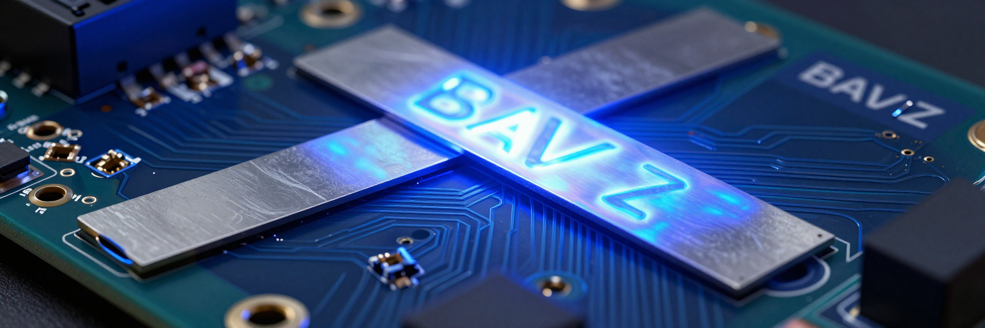
You must look beyond the schematic symbol to understand why the physical construction of the BAV-Z matters. Unlike traditional wire-wound components, these devices utilize a metal strip technology that fundamentally changes how current is measured and heat is dissipated.
Manganin Alloy Composition and Temperature Coefficient (TCR)
The core advantage lies in the Manganin alloy composition. Standard copper or constantan alternatives exhibit significant resistance drift as temperatures fluctuate. In contrast, the BAV-Z maintains a low Temperature Coefficient of Resistance (TCR), typically around 50 ppm/°C. This stability ensures measurement accuracy across extreme ranges from -40°C to +175°C, critical for engine bay environments.
Physical Construction: Metal Element vs. Ceramic Substrate
Analyze the structural design shown in product images, focusing on the direct metal bonding technique. This construction minimizes thermal EMF (thermoelectric voltage) compared to traditional wire-wound shunts. By eliminating solder joints between different metals, you reduce parasitic voltages that can corrupt micro-volt level measurements in precision sensing circuits.
Key Electrical Specifications for Precision Current Sensing
Once the material science is understood, you need to interpret the electrical limits defined in the datasheet. Two parameters dictate performance in fast-switching and high-load scenarios: tolerance and inductance.
Resistance Value Tolerance and Linearity
Break down the ±1% and ±5% tolerance options available in the line. For most BMS applications, ±1% is preferred. However, checking the "Linearity" spec is vital for high-current pulses up to 36W continuous power. Non-linear behavior at peak currents can lead to false state-of-charge readings, so verify linearity curves if your system experiences rapid load transients.
Inductance Characteristics in Fast-Switching Applications
Interpret the low-inductance specifications, often below 1 nH, which are critical for MOSFET switching noise reduction. High inductance causes voltage spikes during fast current changes. You should match shunt inductance with ADC sampling rates in battery monitoring circuits to prevent aliasing errors and ensure clean signal integrity during high-frequency switching events.
| Parameter | Typical Value | Impact on Design |
|---|---|---|
| Resistance (Nominal) | 0.5 mΩ - 50 mΩ | Determines voltage drop range (50-100mV target). |
| TCR | ±50 ppm/°C | Critical for accuracy in varying thermal environments. |
| Inductance | < 1 nH | Minimizes ringing in high-speed PWM circuits. |
| Thermal EMF | < 1 µV/°C | Reduces offset error in DC precision measurements. |
| Power Rating | Up to 36W @ 85°C | Defines maximum continuous current capacity. |
Thermal Management and Power Derating Curves
Power ratings are not static; they depend heavily on ambient conditions. Misinterpreting derating graphs is a common failure point in high-reliability designs.
Interpreting the Power Dissipation Graphs
Guide readers on how to read the derating curves at different ambient temperatures. Note the sharp drop-off above 85°C. Emphasize the difference between peak pulse power and continuous RMS power ratings. A component rated for 36W continuous may handle higher peaks briefly, but sustained operation near the limit accelerates aging and alters resistance values.
PCB Layout Recommendations for Heat Dissipation
Outline best practices for copper pour areas and thermal vias based on manufacturer notes. Adequate copper area acts as a heat sink, lowering the junction temperature. Discuss the impact of airflow and proximity to other heat-generating components on long-term reliability. Poor layout can cause localized hot spots, leading to premature failure despite correct component selection.
Application Scenarios: From EV Batteries to Industrial Drives
Real-world deployment reveals where these specs matter most. Two key sectors rely on precise current sensing for safety and efficiency.
Electric Vehicle Battery Pack Monitoring
In case studies, why BAV-Z is preferred for cell balancing currents in 400V/800V architectures becomes clear. It offers superior vibration resistance relevant to automotive grade standards like AEC-Q200 compliance context. The robust mechanical structure withstands the harsh dynamic loads found in vehicle chassis, ensuring consistent contact resistance over millions of cycles.
Renewable Energy Inverters and Solar Charge Controllers
Analyze suitability for DC link current sensing where efficiency losses must be minimized. Compare BAV-Z performance against alternative high-power shunts in harsh outdoor environments. Its sealed construction resists moisture ingress, making it ideal for inverters exposed to varying humidity and temperature swings without requiring additional conformal coating.
Common Pitfalls in Datasheet Interpretation and Selection
Even experienced engineers miss subtle details. Avoiding these traps saves costly rework.
Ignoring Self-Heating Effects
Warn against assuming room-temperature resistance values apply during operation. Show calculation examples for estimating resistance drift due to self-heating at rated currents. At 100A through a 1mΩ shunt, power dissipation is 10W. This raises the internal temperature significantly, shifting resistance away from the nominal value if not accounted for in calibration algorithms.
Misunderstanding Terminal Configurations
Clarify the difference between Kelvin connections and standard two-terminal setups. Kelvin sensing eliminates lead resistance errors. Provide a checklist for verifying terminal material compatibility with soldering processes. Ensure pads are designed for proper wetting to avoid cold joints, which introduce variable resistance and potential failure points under thermal cycling.
Key Takeaways
- Select BAV-Z for its low TCR and minimal thermal EMF, ensuring stable measurements from -40°C to +175°C.
- Prioritize low inductance (<1 nH) to support fast-switching MOSFETs and accurate ADC sampling in BMS designs.
- Rigorously apply PCB thermal guidelines, using sufficient copper pours to manage derating curves effectively.
- Verify Kelvin connection layouts and account for self-heating drift to maintain precision in high-current applications.
Frequently Asked Questions
What is the main benefit of BAV-Z over wire-wound shunts?
The primary benefit is reduced thermal EMF and lower inductance. Wire-wound shunts generate thermoelectric voltages at solder joints, causing measurement errors in micro-volt ranges. BAV-Z uses a single-piece metal element bonded to ceramic, eliminating these junctions and providing cleaner signals for precision current sensing.
How do I calculate the correct shunt size for my application?
Determine your maximum continuous current and desired voltage drop (typically 50-100mV). Calculate resistance using Ohm's Law (R = V/I). Then, check the power rating (P = I²R) against the derating curve in the datasheet at your expected ambient temperature to ensure safe operation.
Is BAV-Z suitable for automotive AEC-Q200 requirements?
Yes, many variants in this family meet AEC-Q200 standards. They offer high vibration resistance and thermal stability required for automotive environments. Always verify the specific part number's qualification status in the official documentation before finalizing your bill of materials.
Why is Kelvin connection important for BAV-Z shunts?
Kelvin connections separate the current-carrying path from the voltage-sensing path. This eliminates errors caused by lead resistance and contact resistance, which are significant when measuring millivolt-level drops across very low-resistance shunts like the BAV-Z.