MPMT10011002AT5 SOT-23 Divider: Deep Specs & Data Insights
Point: The MPMT10011002AT5 is a compact SOT-23 divider chosen routinely for ADC scaling and sensor front-ends. Evidence: the device combines matched thin‑film resistors in a three‑lead SOT‑23 package optimized for space‑constrained boards. Explanation: engineers pick this part when tight ratio tracking and minimal board area matter, and they consult the official datasheet for exact resistor values, ratio tolerance, and package drawings.
Point: Readers will care about package form factor, resistor ratio/value, and verification steps. Evidence: effective design-in relies on confirmed values from the datasheet and measured tracking behavior. Explanation: this note focuses on those datapoints and on practical test and PCB guidance to validate performance on the bench and in production.
Background: What the MPMT10011002AT5 Is and Where It Fits
Pinout & Package: SOT-23 divider specifics
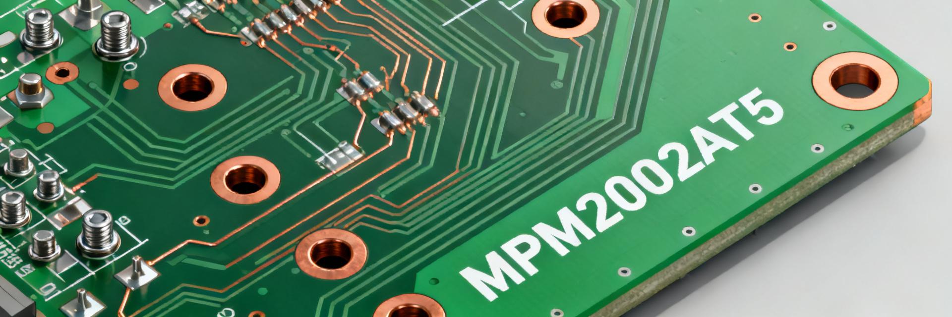
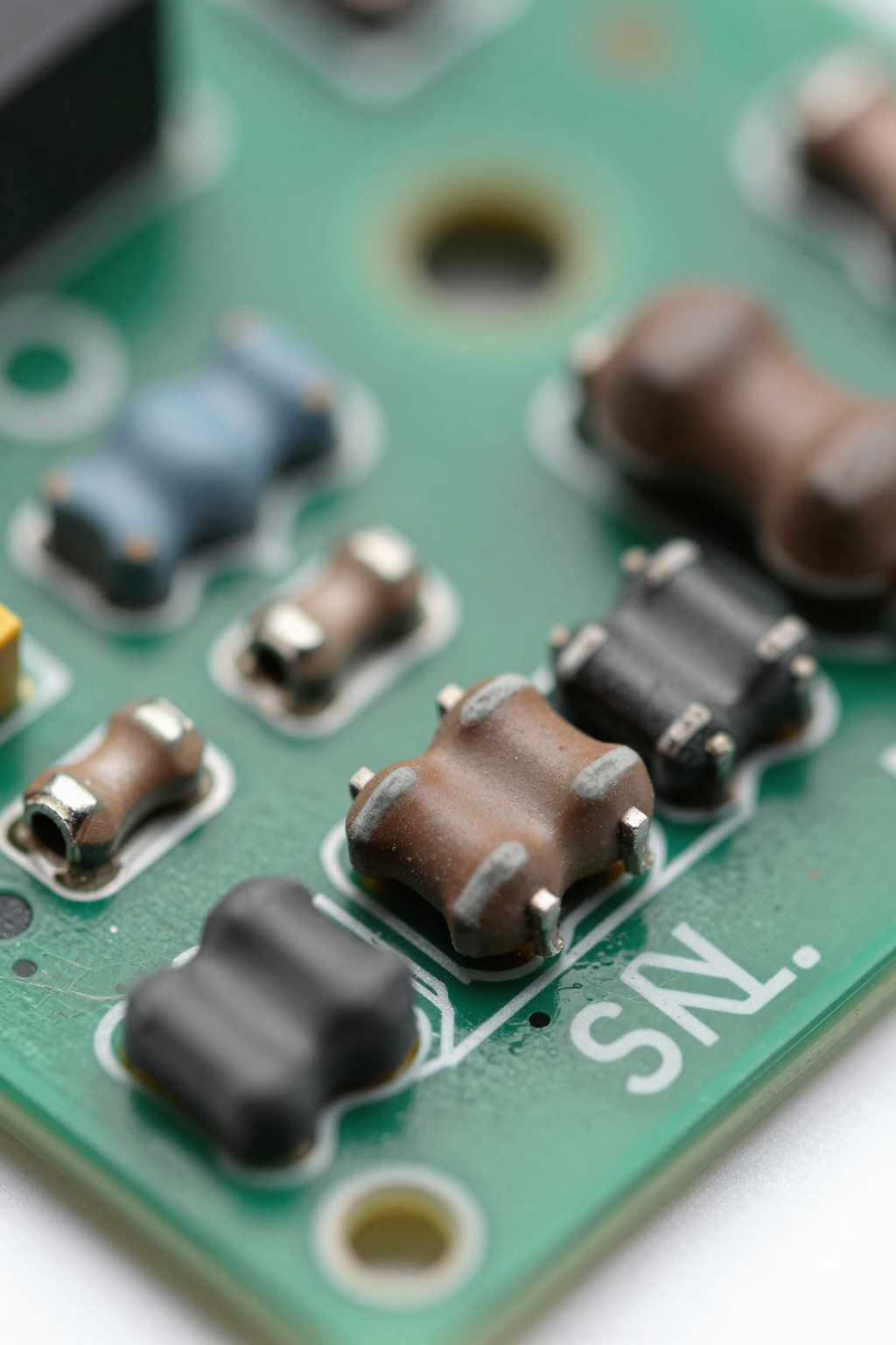
Point: The device uses a standard SOT‑23 / TO‑236‑3 footprint with three leads mapped for two resistor nodes and a common. Evidence: package form enables automated pick‑and‑place and reflow assembly typical of SOT‑23 components. Explanation: for PCB layout use the IPC‑recommended SOT‑23 footprint, align thermal symmetry to preserve matching, and source vendor 3D models (vendor or neutral CAD libraries) for mechanical verification.
Core parameters to pull from the datasheet
Point: Key fields to capture are R1/R2 nominal values, absolute tolerances, ratio tolerance, TCR/TCTR, power per element, max working voltage, noise, and long‑term stability. Evidence: the official datasheet lists these fields and any revision notes that affect acceptance criteria. Explanation: when quoting numeric specs in design or QA, always reference the exact datasheet revision and part marking to avoid mismatches between lots.
Deep Specs & Measured Performance
Ratio accuracy, TCR and tracking behavior
Point: Ratio tolerance (tracking) often controls divider accuracy more than absolute tolerance. Evidence: thin‑film matched networks specify ratio drift and TCR tracking which determine scaled accuracy across temperature. Explanation: evaluate tracking with differential temperature sweeps and drift plots—measure Vout/Vin over temperature and plot percent deviation to validate that ratio tolerance meets system error budget.
Power handling, noise, and frequency response
Point: Power per element and self‑heating can shift ratios; low‑frequency noise and parasitics affect ADC inputs. Evidence: thermal derating curves and noise figures in the datasheet indicate limits; parasitic L/C becomes relevant for high‑speed front‑ends. Explanation: run thermal soak tests (steady‑state power) to quantify self‑heating effect on ratio, and use a network analyzer plus spectrum/noise analyzer for impedance and noise characterization relevant to ADC bandwidth.
Design & Application Guide
Typical circuits and calculation examples
Point: Common uses include scaling 0–5 V into 0–3.3 V for ADCs, sensor bias networks, and high‑impedance inputs. Evidence: divider behavior under load and input bias currents is the practical design constraint. Explanation: calculate divider values including ADC input impedance and op‑amp bias: select R1/R2 to produce desired Vout with minimal loading, then verify using Vout = Vin·R2/(R1+R2) and include input bias induced error in the budget.
PCB layout, thermal and reliability considerations
Point: Layout symmetry and thermal coupling preserve ratio accuracy. Evidence: unequal copper pours or nearby heat sources create gradient‑induced mismatch. Explanation: place the SOT‑23 divider away from hot components, use symmetric copper pours, and add guard traces if needed; follow the vendor’s reflow profile and perform thermal cycling and humidity testing to qualify the assembly process.
Comparative Use Cases & Alternatives
When to choose the MPMT10011002AT5 vs discrete resistors or other divider parts
Point: Choose an integrated thin‑film SOT‑23 divider when tight ratio and matched TCR matter; use discretes when higher power or lower cost dominates. Evidence: integrated networks offer superior tracking and lower temp‑induced differential error versus two separate resistors. Explanation: for small, low‑power sensor front‑ends the SOT‑23 divider reduces calibration needs; for power‑dissipating applications select discrete high‑power resistors instead.
Real-world application examples (sensor front-end, ADC reference, bias networks)
Point: Example sketches include a temperature sensor front‑end where matched ratio minimizes two‑point calibration, and a compact ADC input divider in portable products. Evidence: in practice, matched TCR reduces offset drift and system calibration overhead. Explanation: in each case, specify alternate part characteristics (e.g., higher power rating, lower noise) when application needs differ and validate the tradeoffs by lab testing.
Procurement, Testing & Datasheet Checklist
Datasheet verification checklist
Point: Before acceptance confirm part marking, R1/R2 values, ratio tolerance, TCR (ppm/°C), max voltage, power per element, thermal impedance, solder profile and environmental ratings. Evidence: the datasheet contains these acceptance fields and revision history. Explanation: record the datasheet revision/date and manufacturer cross‑reference in the BOM; reject lots lacking matching markings or documentation.
Sourcing, incoming inspection, and test procedures
Point: Incoming QA should include room‑temperature resistance, ratio checks, and sample thermal cycling. Evidence: ATE vectors that measure R1 and R2 and compute ratio detect lot shifts early. Explanation: use statistically appropriate sample sizes, check reel/tray packaging and lot codes, and define pass/fail criteria based on datasheet tolerances and product QA plans.
| Datasheet Field | What to Record |
|---|---|
| R1 / R2 | Nominal values — record exact numbers from official datasheet |
| Absolute tolerance | Percent tolerance per element — verify on datasheet |
| Ratio tolerance | Matching tolerance between elements — critical for divider accuracy |
| TCR / Tracking | ppm/°C and tracking between resistors — note direction and magnitude |
| Power / Max Voltage | Per‑element dissipation and voltage limits — follow thermal derating |
Key Summary
- The MPMT10011002AT5 provides compact matched thin‑film resistors in a SOT‑23 package; confirm nominal values and ratio tolerance in the official datasheet before design‑in.
- Ratio tracking and TCR govern precision performance; validate with temperature sweeps and drift plots to ensure ADC scaling accuracy in your system.
- PCB layout and thermal symmetry preserve matching; apply symmetric copper, isolate heat sources, and follow recommended reflow and reliability tests.
Common Questions & Answers
How does MPMT10011002AT5 ratio tolerance affect ADC accuracy?
The ratio tolerance directly sets the scaled output error for ADC inputs. Measure actual ratio at operating temperature and include its contribution in the error budget. If the datasheet ratio tolerance exceeds system requirements, add calibration or choose a higher‑precision matched network.
What datasheet items should be checked before purchase?
Check R1/R2 nominal values, absolute and ratio tolerances, TCR (ppm/°C), max working voltage, per‑element power, thermal impedance, and recommended solder profile. Record the datasheet revision and part marking to ensure lot conformity during procurement.
How to test ratio tracking on a thin‑film SOT‑23 divider?
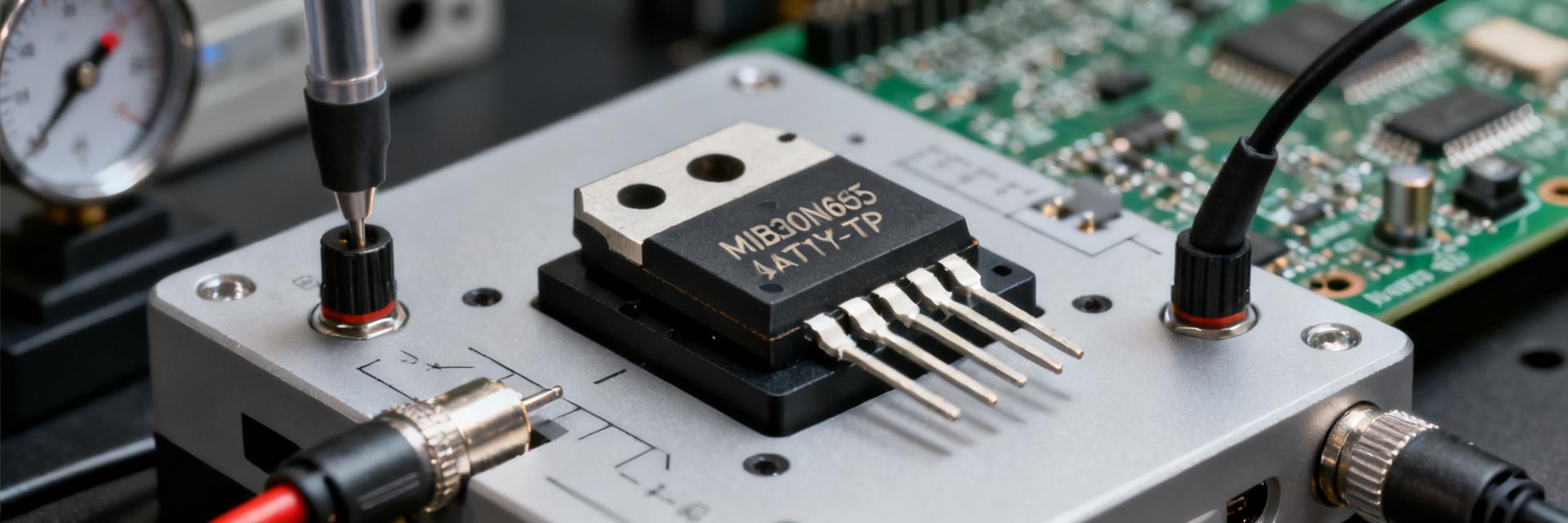
Use a temperature‑controlled chamber to sweep operating range while applying a stable Vin; log Vout and compute Vout/Vin to generate a drift plot. Complement with room‑temp ratio checks on an ATE and perform power‑soak tests to quantify self‑heating effects.
When should I use discrete resistors instead of this integrated divider?
Choose discrete resistors when higher power dissipation capabilities or lower unit cost are the primary drivers. Use the integrated MPMT10011002AT5 when tight ratio matching and minimal board area are critical for sensor front-ends or ADC scaling.
Conclusion
Point: The MPMT10011002AT5 is a space‑efficient, precision thin‑film SOT‑23 divider suited for ADC scaling and sensor front‑ends. Evidence: its matched elements and SOT‑23 footprint reduce calibration and board area compared with discrete assemblies. Explanation: before design‑in, consult the official datasheet for exact R1/R2, ratio tolerance and TCR, apply the PCB/layout tips above, complete the datasheet checklist, and run incoming tests to verify lot performance.