HoFL3-6918-C 50 µOhm Shunt: Performance Datasheet & Limits
Typical spec sheets list a nominal resistance of 50 μΩ and rated power figures around the mid‑30 watt range; this yields a theoretical thermal-limited current near 850 A. Practical continuous ratings for the HoFL3-6918-C are lower — commonly 300–700 A — once mounting, ambient, and derating are considered. This article explains how to translate datasheet entries into safe currents and integration checks.
The purpose is to give engineers concise calculation steps, derating rules, and test protocols to validate a 50 μOhm shunt resistor in system use. Key datapoints covered include nominal R, tolerance/TCR, rated power, thermal resistance concepts, measurement setup, and an actionable procurement/testing checklist engineers can apply in lab validation.
1 — Quick product overview: HoFL3-6918-C key specs (background)
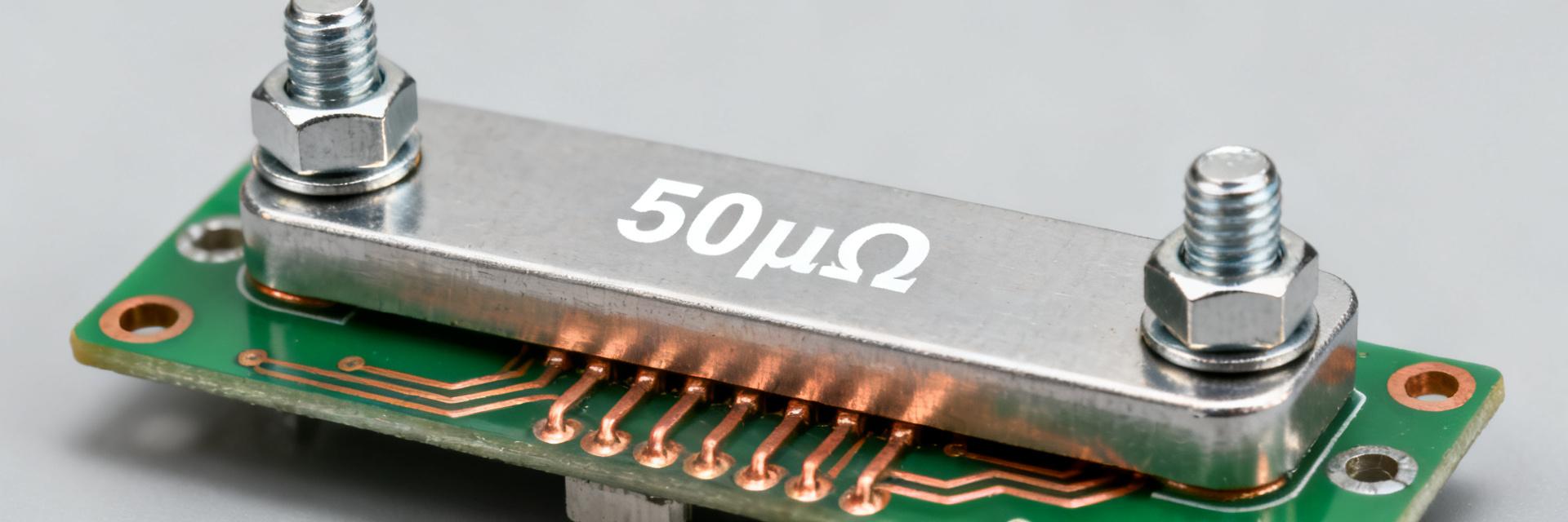
1.1 Nominal electrical specs to list and verify
Point: Nominal resistance 50 μΩ, tolerance options typically ±0.5% or ±1.0%, TCR commonly in the ±50 ppm/°C range, and rated power frequently near 36 W. Evidence: datasheet style tables present these values. Explanation: Verify R, tolerance, TCR, and Pmax against your measurement capability and system error budget before integration.
| Parameter | Value | Conditions / Remarks |
|---|---|---|
| Nominal Resistance | 50 μΩ | Measured at 20°C via Kelvin connection |
| Rated Power (Pmax) | 36 W | Requires adequate system heatsinking |
| Tolerance Options | ±0.5% / ±1.0% | Selectable based on system budget |
| TCR | ±50 ppm/°C | Over -40°C to +125°C range |
1.2 Mechanical footprint, mounting and environmental ratings
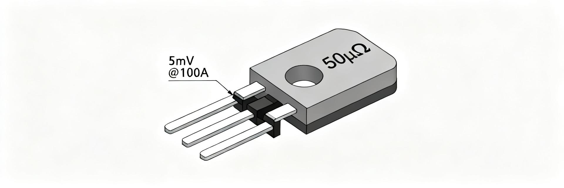
Point: The shunt package has a compact rectangular footprint with terminal pitch ≈52 mm and bolt terminals for low contact resistance. Evidence: mechanical specs define torque and operating temperature ranges. Explanation: Mounting torque, insulators, and thermal path to chassis strongly affect continuous dissipation and measurement stability; verify terminal clamp method and ambient envelope.
2 — Datasheet electrical performance breakdown (datasheet)
2.1 DC resistance, tolerance, and measurement expectations
Point: Nominal 50 μΩ is a reference at specified temperature and measurement method (often four‑terminal). Evidence: datasheet notes measurement conditions and allowed drift. Explanation: In-circuit readings vary with lead resistance, Kelvin placement, and meter resolution; use sub‑milliohm bridges or precision ADCs with proper sense wiring to resolve <0.1% changes.
2.2 TCR, long-term stability, and aging behavior
Point: TCR (ppm/°C) governs resistance shift with temperature; life tests indicate long-term drift under rated stress. Evidence: stability figures on datasheets show ppm/year or percent after X cycles. Explanation: Expect small but measurable drift after thermal cycling or sustained high current; include TCR in accuracy budgets and schedule validation cycles for qualification.
3 — Thermal behavior, power dissipation and derating limits (data analysis)
3.1 Theoretical vs. practical current limits (calculation method)
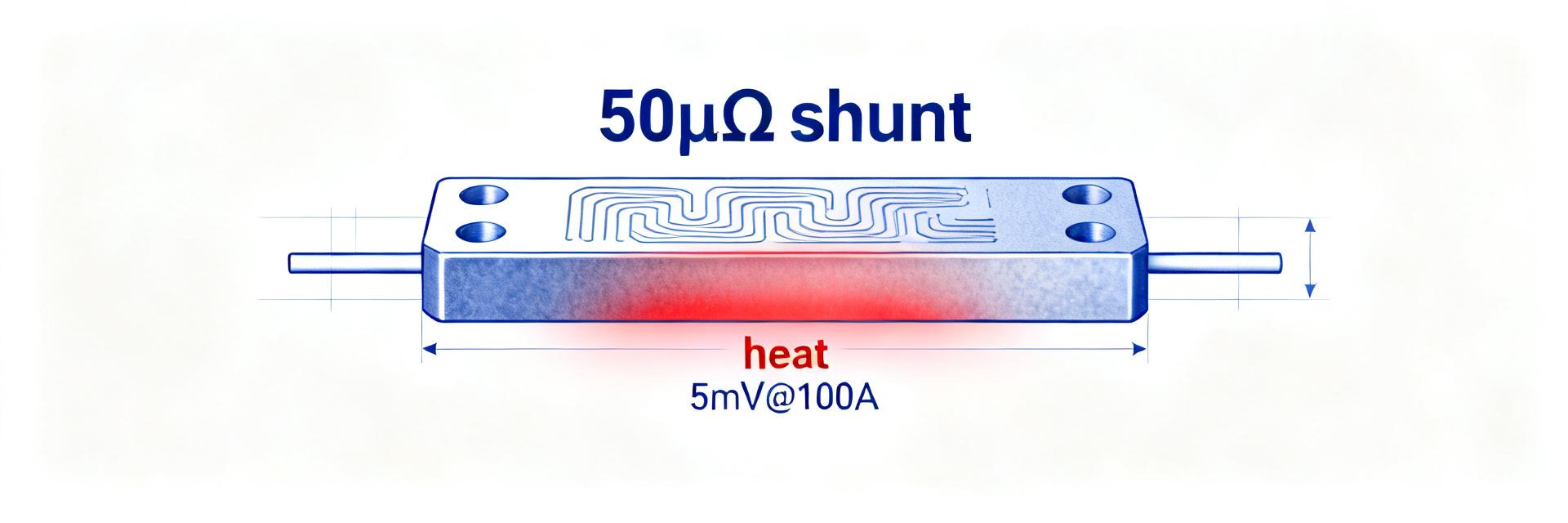
Point: Thermal-limited current Imax = sqrt(Pmax / R). Evidence: using R=50 μΩ and Pmax=36 W yields Imax ≈ 849 A. Explanation: That is a steady‑state thermal limit under ideal cooling; practical continuous current is lower due to limited thermal path, PCB conduction, and ambient, so use derating factors and conservative duty cycles for continuous operation.
3.2 Thermal resistance, thermal time constant and derating curves
Point: Thermal resistance (°C/W) and time constant define short‑pulse vs steady behavior. Evidence: datasheet thermal diagrams or measured ΔT vs power inform curves. Explanation: Produce derating curves by measuring case or PCB temperature rise at several power levels and ambient points; use time constants to specify safe pulse energy and RMS limits for intended duty cycles.
4 — Measurement and test best practices for accurate datasheet validation (method)
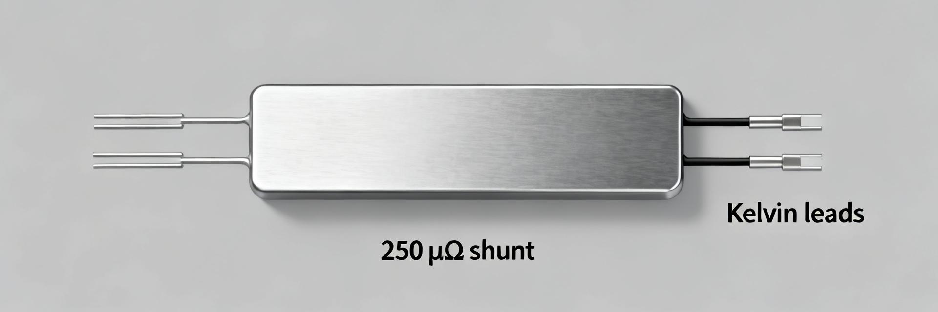
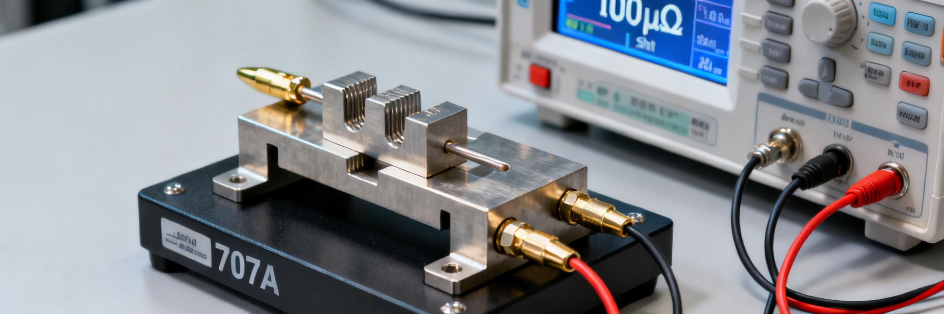
4.1 Four-wire (Kelvin) measurement setup and tolerances
Point: Kelvin sense with short leads and low thermal EMF junctions is essential. Evidence: recommended fixture sketches place sense leads adjacent to terminals. Explanation: Use precision DMMs or microohm bridges with resolution better than 0.01% of 50 μΩ, sample averaging, and guard against thermal EMFs by reversing polarity or using AC methods for highest accuracy.
4.2 Thermal testing: transient and steady-state protocols
Point: Combine pulse bench tests and steady-state ramps to map derating. Evidence: thermocouple placed on shunt body and nearby PCB tracks yields reproducible curves. Explanation: Recommended protocol: start with short pulses to characterize thermal mass, then step power for steady-state points; document ambient, fixture, and measurement timing to reproduce derating curves.
5 — Design integration and circuit guidance (method)
5.1 Mechanical and PCB integration: minimizing thermal resistance
Point: Bolted mounting, large copper pours, and thermal vias reduce junction-to-ambient thermal resistance. Evidence: thermal modeling and measured ΔT improvements with heat spreaders. Explanation: Increase copper area, use multiple vias under the shunt, and provide a direct conductive path to chassis or heatsink to raise continuous current capability and stabilize resistance under load.
5.2 Sensing circuit considerations: amplifier, filtering, and accuracy budget
Point: μΩ‑level voltages require low‑offset amplifiers, proper common‑mode handling, and filtering. Evidence: amplifier gain choice and ADC LSB size determine quantization error. Explanation: Build an accuracy budget combining shunt tolerance, TCR, amplifier offset, and ADC noise; for example, ±0.5% shunt + 100 μV amplifier error can dominate percent error at low currents.
6 — Application examples, failure modes and action checklist (case + action)
6.1 Typical applications and observed limits (BMS, chargers, power supplies)
Point: Typical uses include battery management, charger sensing, and power supply current monitoring. Evidence: expected continuous ranges differ: BMS 300–500 A, chargers 400–700 A bursts. Explanation: For continuous BMS duty target conservative currents with large copper thermal paths; for charger pulses rely on short‑pulse thermal capacity and confirm with measured derating curves.
6.2 Failure modes, troubleshooting tips and procurement checklist
Point: Common failures stem from overheating, poor mounting, and environmental corrosion. Evidence: symptom triage includes elevated resistance, thermal hotspots, and intermittent contact. Explanation: Procure with required tolerance, TCR, documented derating curves, and sample life-test reports; verify mounting hardware, specify torque, and run acceptance thermal cycling tests before mass deployment.
Summary
- The HoFL3-6918-C nominal R = 50 μΩ and typical Pmax ~36 W allow a theoretical Imax ≈ 850 A, but practical continuous current is lower due to thermal path and mounting.
- Measure with four‑wire methods, include TCR and amplifier error in the accuracy budget, and produce derating curves for ambient and fixture conditions.
- Use robust mechanical fastening, copper pours, and thermal vias to increase continuous capacity; validate with pulse and steady tests before approval.
FAQ
What is the maximum continuous current for HoFL3-6918-C-50uR-0.5% in typical BMS installations?
Continuous current depends on thermal path; typical validated ranges for battery management applications fall between 300–500 A when mounted to a PCB with substantial copper and proper thermal vias. Always derive a site-specific derating curve and verify with steady-state thermal measurements.
How should I test HoFL3-6918-C-50uR-0.5% for pulse vs steady-state limits?
Run short pulse tests to characterize thermal mass (measure ΔT vs energy), then perform stepped steady-state power tests to map ΔT vs power at given ambient conditions. Use thermocouples on the shunt body, and ensure fixture repeatability; derive RMS limits for your duty cycle from those measurements.
What measurement accuracy can I expect when using HoFL3-6918-C-50uR-0.5% for low-current sensing?
At low currents the μΩ-level drop becomes small; expect amplifier offset and ADC quantization to dominate. With ±0.5% shunt tolerance, a low‑offset amplifier and a 24‑bit delta‑sigma ADC or precision bridge are needed to keep total error below 1% across your operating range.
What is the recommended mounting torque and bolt specification for the HoFL3-6918-C to minimize contact resistance?
To ensure minimal and stable contact resistance, secure the HoFL3-6918-C terminals using M8 high-tensile steel bolts tightened to a nominal torque of 12 to 15 N·m. Always use flat and split washers to maintain constant pressure over thermal cycles.