HoFL3-6918-C-50uR-1: Datasheet Deep Dive — 50µΩ Specs
The HoFL3-6918-C-50uR-1 appears here as a representative ultra-low-ohm device; its nominal resistance of 50 µΩ drives defining trade-offs in voltage drop, power loss, and measurement resolution. This practical, datasheet-centered deep dive focuses on how those numbers translate to selection, verification, and system integration for engineers validating a 50 µΩ class shunt for high-current sensing.
Readers will get an at-a-glance spec summary, worked TCR and power-derating guidance, measurement best practices for µΩ-level parts, and a compact validation checklist suitable for incoming inspection and production. Emphasis remains on datasheet test conditions, repeatable measurements, and concrete pass/fail criteria engineers can apply immediately.
Product overview & key specs (background)
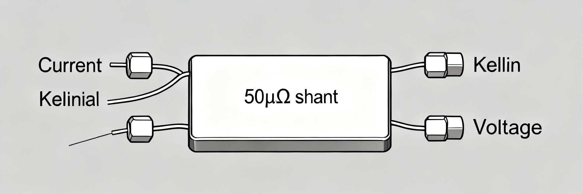
Mechanical & electrical snapshot
Key datasheet values (quoted): nominal resistance 50 µΩ, tolerance class typically ±0.5% or ±1%, rated power (continuous) per part marking, typical pitch/length and mounting style as specified, recommended mounting torque, and a listed TCR in ppm/°C. When selecting, quote the datasheet’s stated ranges and any optional trims exactly to avoid mismatched expectations in measurement and reliability.
| Spec | Typical Datasheet Value |
|---|---|
| Nominal resistance | 50 µΩ |
| Tolerance | ±0.5% / ±1% variants |
| Rated power | See datasheet continuous rating |
| Mounting | Through-hole / bolted options |
| TCR (typical) | Specified in ppm/°C |
Part-number decoding & variant notes
The part code encodes series, resistance, tolerance, and lead/term style; for example the mid-segment refers to nominal resistance and the suffix indicates tolerance or lead form. Watch close variants: suffixes can change tolerance or continuous power rating. Always confirm the full part code from the datasheet before procurement to avoid subtle spec differences.
- C: mechanical/connector style indicator — check mounting options.
- 50uR: nominal 50 µΩ resistance.
- -1 or other suffixes: tolerance or packaging variant — confirm power rating.
Electrical performance deep-dive (data analysis)
Resistance tolerance, temperature coefficient, and stability
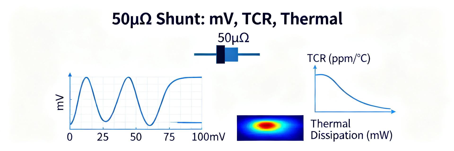
Tolerance class directly sets initial uncertainty; for a 50 µΩ device a 0.5% tolerance equals ±0.25 µΩ. TCR given in ppm/°C converts to µΩ/°C: ΔR = R × (TCR × 1e-6) × ΔT. For example, a 50 µΩ part with 50 ppm/°C over a 40°C delta yields ΔR = 50µΩ × 50e-6 × 40 = 0.1 µΩ, which matters when targeting sub-millivolt measurements at high current. Use the datasheet test conditions when extrapolating.
ΔR = R × TCR(ppm/°C) × 1e-6 × ΔT. Example: 50 µΩ, 50 ppm/°C, ΔT 40°C ⇒ ΔR = 0.1 µΩ.
Power rating, thermal behavior & derating
Datasheet continuous power rating and any thermal resistance numbers define the thermal rise under current: P = I²R. Derating curves specify allowed ambient power as mounting and airflow change. Treat thermal rise as a driver for resistance drift and lifetime; adopt a conservative SOA that keeps part temperature well below maximum specified node to limit TCR-induced errors and reliability risk.
Accuracy, measurement & test considerations (data analysis)
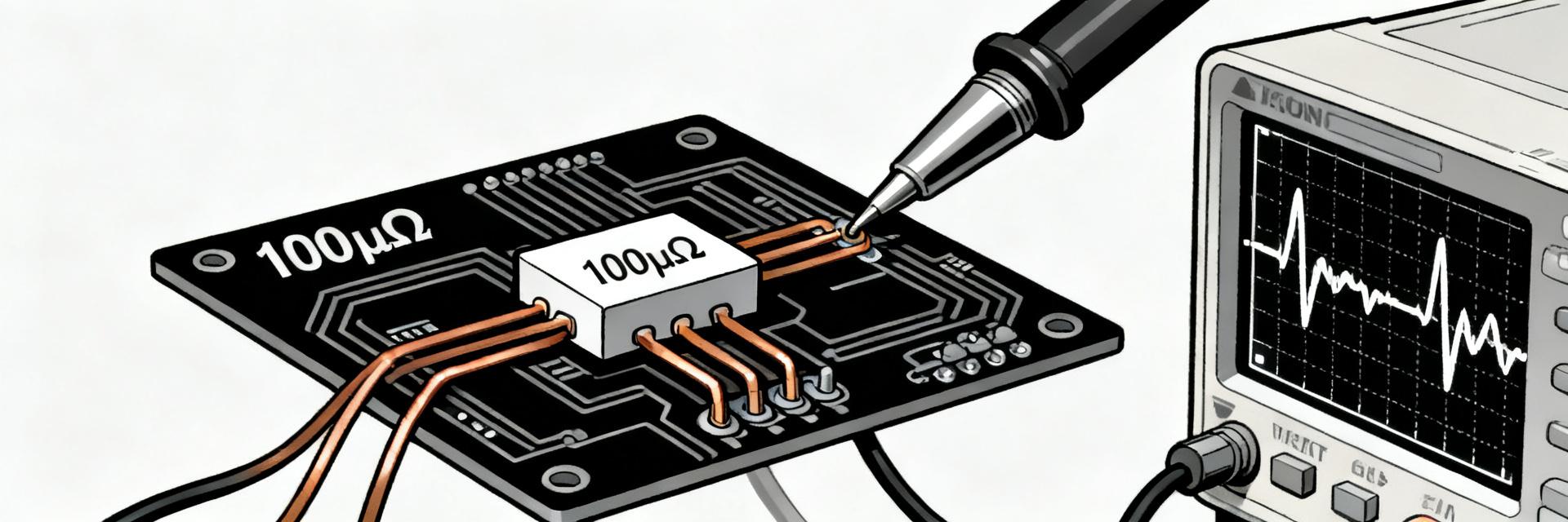
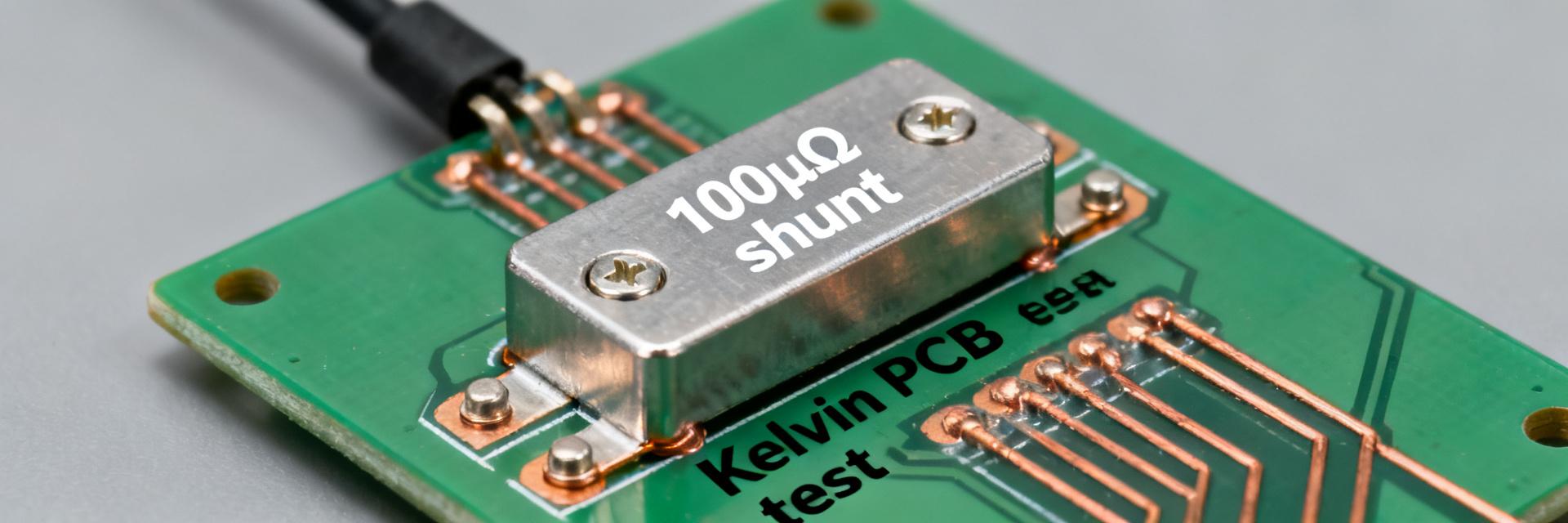
Proper measurement technique: four-wire/Kelvin sensing
For µΩ-level parts always use four-wire Kelvin connections: dedicated current and sense leads minimize lead resistance influence. Select test currents that produce measurable voltage without inducing unacceptable self-heating — typically 10–50% of rated continuous current for cold resistance, and up to rated current for operational verification. Mitigate contact resistance by using clean, torqued hardware and short sense lead paths.
- Use low-thermal EMF connectors and symmetric lead routing.
- Torque mounting hardware per datasheet before measurement.
- Allow thermal equilibrium between successive tests.
Noise, long-term drift & environment effects
Noisy front-ends, vibration, humidity, and thermal cycling introduce drift beyond initial tolerance. Datasheet stability or drift parameters guide acceptable change over time; for production validation, specify accelerated thermal cycle and humidity tests and measure resistance and TCR before/after. Define pass/fail thresholds (e.g., <0.2% shift after X cycles) tailored to your system’s resolution needs.
Application guidelines & design integration (methods/guides)
PCB layout, mounting & thermal management
Layout rules: provide wide copper for main current path, separate thin sense traces for Kelvin connections, and keep sense vias and traces away from heat sources. Use thermal relief patterns that spread heat to planes or a heatsink. Follow datasheet mounting torque to avoid mechanical strain; improper fastening can change contact resistance and mechanical stability under cycling.
- Place sense pads within 2–5 mm of shunt terminals.
- Use multiple vias on current path to reduce local heating.
- Document torque and reflow/solder instructions from datasheet.
Sizing & use-case recommendations
Choose the variant by balancing voltage drop V = IR and power loss P = I²R. Example scenarios: for a 100 A battery monitor, V = 100A × 50µΩ = 5 mV and P = 0.5 W; for a 10 A precision sense, V = 0.5 mV and P = 0.005 W. Higher currents demand thermal strategies; lower currents emphasize tolerance and TCR for resolution.
| Use case | Vdrop | Power |
|---|---|---|
| 100 A monitor | 5 mV | 0.5 W |
| 10 A precision | 0.5 mV | 0.005 W |
Real-world validation, selection checklist & troubleshooting (case study + action)
Short real-world example (selection → test → result)
Selecting this part for a 200 A battery monitor: expected V = 200A × 50µΩ = 10 mV and P = 2.0 W continuous; the project required ±0.1% resolution, so select the tighter tolerance variant and verify TCR per datasheet. Bench test measured cold resistance within datasheet tolerance and thermal rise matched predicted derating curve when mounted to an aluminum carrier.
| Metric | Expected | Measured |
|---|---|---|
| Cold R | 50 µΩ ±0.5% | 50.1 µΩ |
| Thermal rise @200A | Predicted per derating | Within 10% of prediction |
Procurement, inspection & troubleshooting checklist
Incoming inspection should verify part marking, mechanical dimensions, and cold resistance measurement. For a 50µΩ shunt specify measurement current, torque, and allowed resistance delta. Log TCR when required and run an initial thermal test. If failures occur, check mounting torque, contact cleanliness, and whether solder or clamp methods introduced mechanical stress or excess thermal resistance.
- Verify part code and marking against purchase order.
- Measure cold R at defined test current and record results.
- Perform a short thermal ramp test and compare to datasheet derating.
Summary (conclusion & call-to-action)
Choosing and validating a 50 µΩ device demands attention to tolerance, TCR, rated power, and thermal integration; the HoFL3-6918-C-50uR-1’s datasheet values guide conservative design and repeatable measurement. Confirm part-code variants, adhere to mounting torque, use four-wire measurement, and apply the checklist above. Share measured results or questions to refine acceptance thresholds for your application.
Key summary
- Confirm nominal 50 µΩ and tolerance variant from the datasheet before procurement; small percentage differences materially affect millivolt-level sensing.
- Calculate TCR impact using ΔR = R × TCR(ppm/°C) × 1e-6 × ΔT and include thermal derating in SOA decisions to limit drift and maintain accuracy.
- Measure with four-wire Kelvin technique, follow datasheet torque and mounting guidance, and run a short thermal validation to verify real-world behavior against datasheet curves.
Common questions & answers
How to measure a 50 µΩ shunt accurately?
Use a four-wire Kelvin setup, stable current source, and a high-resolution voltmeter or DAQ. Apply a test current that yields a measurable voltage (for example, 10–50% of rated current for cold resistance) and allow the part to reach thermal equilibrium for operational checks. Minimize thermoelectric EMFs and ensure torqued, clean contacts.
What tolerance and TCR should I expect from a 50 µΩ shunt?
Tolerance options commonly include ±0.5% and ±1%; TCR is provided in ppm/°C on the datasheet and must be converted to µΩ/°C for system impact assessment. Use the datasheet’s test conditions when comparing parts, and include TCR in worst-case drift budgets for temperature excursions.
How do I validate thermal performance against the datasheet?
Perform a controlled current ramp to the intended operating current while monitoring temperature and resistance. Compare measured resistance shift and temperature rise against the datasheet’s derating curve and thermal resistance figures. Define pass/fail limits (for example, <0.2% resistance shift at rated current) appropriate to system resolution needs.
What is the key PCB layout rule for Kelvin connections?
Place sense pads within 2–5 mm of shunt terminals, route thin sense traces symmetrically away from heat sources, and use wide copper with multiple vias for the primary high-current path to reduce local heating.