25µΩ shunt resistor: in-depth spec comparison & data
At 50 A a 25µΩ shunt resistor produces 1.25 mV and dissipates 0.0625 W; at 100 A it yields 2.5 mV and 0.25 W; at 500 A it yields 12.5 mV and 6.25 W. These concrete numbers show the millivolt-scale outputs and multi-watt losses designers must balance between measurement resolution and thermal management.
What is a 25µΩ shunt resistor — core functions & physical forms
Current sensing uses Ohm’s law (I = V/R): a small known resistance converts current to a millivolt-level voltage. A 25µΩ value is chosen when high currents and minimal voltage drop are priorities—battery packs, busbars, and high-current power stages. The low millivolt output requires high-resolution ADCs or precision amplifiers to meet accuracy goals in high-current systems.
Typical materials and mechanical considerations
Common forms include bolted bar/strip shunts, riveted assemblies, and thin metal-foil or PCB shunts. Alloys like manganin or constantan reduce TCR and thermal EMF; copper-based strips increase conductivity but need Kelvin sensing. Trade-offs center on thermal mass, mounting footprint, and availability of Kelvin pins for low-error sensing.
Electrical specifications you must compare
Resistance value, tolerance, and TCR
Nominal 25µΩ tolerance (±0.5% vs ±5%) directly affects measurement error: at 100 A a ±1% tolerance is ±0.025 mV error on a 2.5 mV signal. TCR (ppm/°C) causes drift: a 50 ppm/°C TCR over a −40 to +85 °C span shifts R by ~0.625% — significant for state-of-charge or power metering.
Power rating and thermal resistance
Use P = I²R to compute dissipated power and then ΔT = P × θJA to estimate temperature rise. Prefer parts with published ΔT vs. I curves and thermal time constants rather than single-number ratings to understand transient thermal behavior.
How to perform a spec comparison: practical checklist
| Part Profile | Tolerance | TCR (ppm/°C) | I-Continuous (A) | Primary Application |
|---|---|---|---|---|
| Profile A | ±0.5% | 40 | 200 | Precision Metrology |
| Profile B | ±1.0% | 100 | 400 | High-Current Robust Bar |
| Profile C | ±5.0% | 300 | 500 | Rugged High-Mass Copper |
Integration, testing, and verification checklist
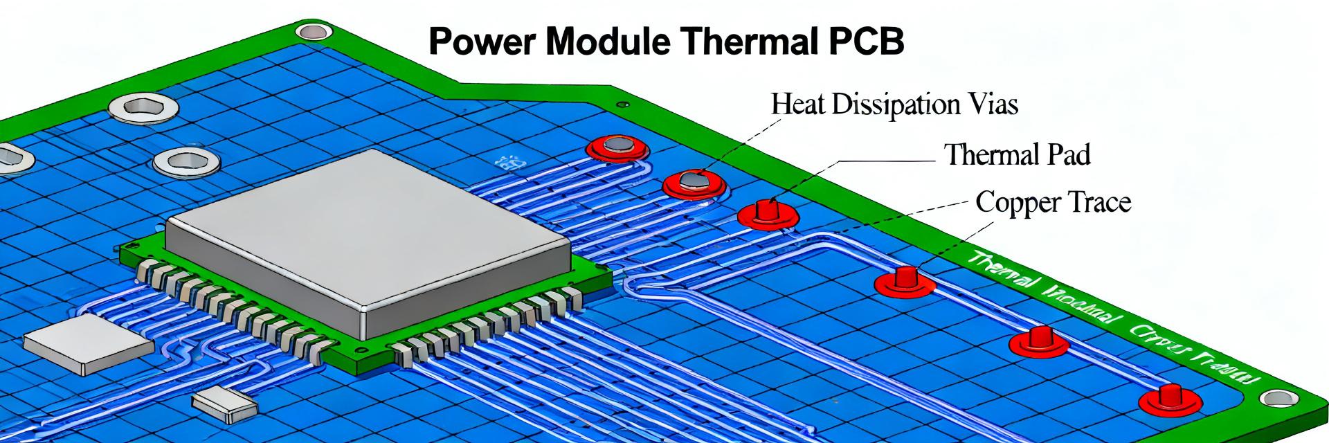
- Mounting: Bolt to thermally conductive pads or busbars; include heatsinking or airflow.
- Sensing: Use 4-terminal Kelvin connections to remove lead resistance from the measurement.
- ADC Selection: Choose amplifiers with low offset and gain matched to the sub-15mV range.
- Validation: Perform stepped-current DC accuracy tests across the full temperature range.
Summary
Choosing a 25µΩ shunt resistor requires balancing tolerance, TCR, thermal performance, and mounting. Lower tolerance and lower TCR improve measurement accuracy but often cost more; higher-mass parts survive transients better but drift more with temperature.
Key summary
- At high currents, 25µΩ still yields multi-watt losses; balance Vdrop and accuracy carefully.
- Compare ΔT vs. I curves rather than static power ratings to predict real-world behavior.
- Use Kelvin sense and thermal monitoring to achieve reliable, repeatable measurements in EV and industrial drives.
Frequently Asked Questions
How do I verify a 25 µΩ shunt resistor's accuracy in my system?
Verify by applying calibrated stepped current profiles while logging differential voltage and temperature. Use a high-precision DVM and thermocouples; perform DC accuracy across temperature, measure long-term drift, and run thermal cycling. Compare measured R vs. datasheet TCR and adjust calibration accordingly.
What mounting practices reduce error for a 25 µΩ shunt?
Use solid mechanical mounting to a thermally conductive plane or busbar, employ Kelvin connections for sense leads, minimize sense lead length, and avoid routing sense traces near high-current loops. Add local temperature sensing for compensation and ensure consistent thermal contact during assembly.
Which tests catch thermal EMF and transient issues for 25 µΩ shunts?
Perform polarity-reversal tests to reveal thermal EMF, short-duration high-current pulses to observe transient heating, and FFT/noise tests on the front-end to detect EMI-coupled errors. Combine thermal imaging or thermocouples with voltage logging to correlate temperature gradients to measurement drift.
Why is TCR critical for high-current shunts?
Temperature Coefficient of Resistance (TCR) determines how much the 25µΩ value changes as the part self-heats. High-current loads can raise internal temps by 50°C+, which with a poor TCR, leads to significant drift in current readings and SOC estimation errors.