W8420-3.0-2-050 shunt resistor: Safety Data & Mounting Tips
The W8420-3.0-2-050 shunt resistor is a low-ohmic current-sense element (≈50 μΩ ±15%) with a 36 W rated dissipation and a flat-bar form factor (~84 × 20 × 3 mm with two mounting holes). In practical systems this class of shunt is used where accurate measurement at tens to hundreds of amps is required; thermal rise, contact resistance and mechanical fixation directly determine accuracy and safety. This article presents measured- and design-oriented data, safety data and mounting tips so technicians and engineers can install and validate the W8420-3.0-2-050 shunt resistor reliably.
1 — Product overview & where it fits (background)
Key electrical specs: nominal resistance ≈50 μΩ (±15%), power rating 36 W, appropriate for continuous currents when properly cooled. At 100 A the nominal voltage drop is about 5 mV and dissipation is 10 W (P = I²·R). Such small voltage drops require low-noise amplification and attention to ADC input range and amplifier gain to preserve resolution without saturating inputs.
Key electrical specs to note
Nominal resistance: 50 μΩ, tolerance ±15%, rated power 36 W. Example: at 50 A Vdrop ≈2.5 mV, P ≈2.5 W; at 200 A Vdrop ≈10 mV, P ≈40 W (exceeds rating unless pulsed/air-cooled). Consequences for front-ends: choose instrumentation amplifiers with microvolt-level offset performance or use a Kelvin-sense arrangement and set gain so full-scale corresponds to expected peak currents.
Mechanical form & procurement considerations
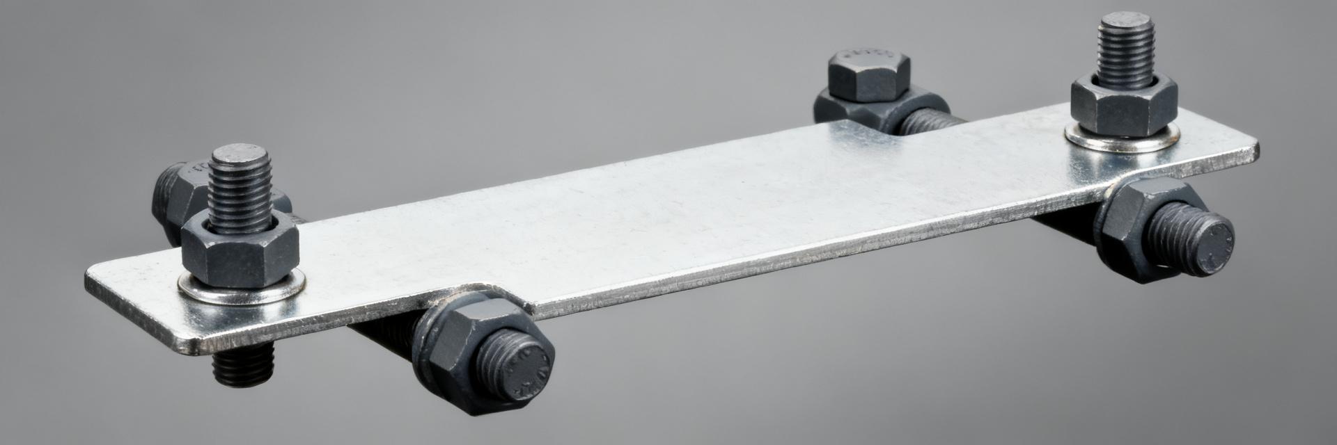
Dimensions: 84 × 20 × 3 mm with two mounting holes; recommended fastener sizes typically M4–M6 depending on hole clearance and busbar thickness. Handling notes: avoid bending the flat bar and avoid touching contact faces with bare hands to limit contact resistance. During procurement check hole tolerance and material finish to ensure reliable contact and mechanical fit.
2 — Safety data & limits (data analysis)
Thermal performance and derating are central to safety data. Use P = I²·R to compute dissipation and then estimate temperature rise using a conservative thermal resistance (for example, 5–10 °C/W for a compact mounted shunt without forced airflow). Continuous current limits depend on enclosure airflow: a 36 W rating assumes adequate conduction to mounting hardware and reasonable ambient; derate for higher ambient or restricted airflow.
Thermal performance & derating
Worked example: at 100 A, P = 100² × 50e‑6 = 10 W; with a conservative thermal resistance of 6 °C/W the expected rise is 60 °C above ambient. If ambient is 25 °C the shunt case could reach ~85 °C; keep below conservative max component temp (recommend 70–100 °C depending on nearby insulation and connectors). For short pulses the shunt can tolerate higher instantaneous power; verify with duty cycle thermal modelling.
Electrical safety and fault scenarios
Open-circuit sense wiring can expose amplifiers to high common-mode voltages; use input protection and isolation where necessary. Contact resistance growth over time increases localized dissipation and hot spots—inspect contacts at regular intervals (recommended initial check after 100 hours and then periodically). Fault scenarios such as a wiring short to chassis or overload require upstream protection sized to disconnect before thermal damage occurs.
3 — Mounting & mechanical best practices (methods — mounting tips)
Fastening torque, washer and surface prep directly affect contact resistance and measurement stability. Recommended fasteners: M4–M6 stainless or plated bolts with a conservative torque window (e.g., M4: 1.5–2.5 N·m; M5: 3–5 N·m; M6: 5–8 N·m) — verify on first unit by measuring contact resistance while increasing torque. Use flat washers to distribute load and lock washers or threadlocker for vibration environments.
Fastening torque, washer and surface prep
Surface prep: clean mating surfaces of oxidation and oil; use an approved conductive contact compound only if the compound's stability and effect on measurement accuracy are validated. If manufacturer torque is unavailable, apply conservative torque and then measure Kelvin resistance to verify stability. Re-torque after initial thermal cycling to compensate for settling.
Mechanical support & vibration mitigation
Prevent bending and cyclic stress with support brackets or insulating spacers under the shunt ends. For mobile or industrial applications, recommend medium-strength threadlocker and captive hardware or mechanical clips; add rubber-isolated mounts if needed. Mechanical stress induces metallurgical strain and contact variation that leads to measurement drift over time.
4 — Electrical integration & measurement setup (methods — calibration & wiring)
Route sense leads as close as practical to the shunt contact to minimize lead-induced error; use dedicated Kelvin sense connections. Ground and common-mode strategy: prefer differential amplifiers or isolated measurement modules when sensing high common-mode voltages. Keep sense pair twisted and short, and avoid routing near noisy switching paths.
Routing, grounding and common-mode considerations
Place amplifier inputs within the ADC common-mode range or add isolation. In high-voltage systems use isolated amplifiers/modules. Avoid ground loops by referencing the measurement amplifier appropriately and tying sense return at a single point. Shielding may help in electrically noisy environments.
Calibration, offset compensation & verification
Calibration checklist: zero-current offset (short shunt leads), span calibration with a known load or calibrated current source, and temperature drift compensation using a table or linearized coefficient. Verification cadence: initial bench calibration, verification after first power-up under load, and periodic field checks (compare to a calibrated clamp meter or known precision resistor).
5 — Application examples & compatibility checks (case)
Typical use cases: battery management (charging/discharging currents 10s–100s A), motor drives (high peak currents, pulses), and power supplies. In battery systems expect continuous currents up to the design limit; in motor drives expect thermal cycling and higher peak duty that require more conservative continuous-current derating.
Typical use cases and expected behaviors
Enclosure airflow and mounting mass greatly affect allowable continuous current. For example, a shunt in free airflow mounted to a substantial heatsinking busbar will carry significantly more continuous current than the same shunt bolted to a small insulated spacer. Account for this in system current budgets.
Interoperability with sensing electronics
Match shunt resistance and amplifier gain to achieve the desired resolution and noise floor. Low-side sensing is simpler electrically but may create common-mode ground currents; high-side sensing requires amplifiers tolerant of common-mode voltage or isolation. Ensure input protection against transients and test for amplifier offset stability under expected thermal cycles.
6 — Quick action checklist & troubleshooting (action)
Pre-install checklist: verify orientation, torque, clean contact surfaces, tight wiring, amplifier input protection and ventilation. Quick safety checks: continuity and shorts, and perform a thermal scan after initial power-up to find hot spots early. Use the table below for quick reference values and guidance.
| Current | Vdrop | Power | Recommended use |
|---|---|---|---|
| 50 A | ≈2.5 mV | ≈2.5 W | Continuous with minimal cooling |
| 100 A | ≈5 mV | ≈10 W | Continuous with heatsinking or airflow |
| 200 A | ≈10 mV | ≈40 W | Pulse only; exceeds continuous rating unless heavily cooled |
Pre-install checklist (mounting tips + safety data)
Verify fastener torque and measure contact resistance after installation. Confirm amplifier dynamic range and protection. Validate ventilation and place a temperature sensor near the shunt for early detection of abnormal heating during commissioning.
Field troubleshooting steps
Symptoms and actions: unexpected voltage drop → verify torque and clean contacts; thermal drift → improve cooling or add temperature compensation; intermittent readings → check for loose hardware or vibration damage. Replace the shunt if contact surfaces are visibly corroded or if resistance has shifted beyond tolerance after corrective actions.
Frequently Asked Questions
What causes unexpected output voltage drop anomalies in high-current operation?
Unexpected voltage drops usually stem from insufficient contact bolt torque, oxidized mating surfaces, or micro-gap contact degradation under thermal load. Verifying fastener torque and re-polishing contact interfaces cures contact-induced deviations.
Why is Kelvin 4-wire sensing mandatory for the 50 μΩ W8420 shunt?
At 50 μΩ, lead resistance and standard contact interface resistance can match or exceed the shunt value itself. Kelvin sense taps isolate the current-carrying path from the signal detection circuit to eliminate parasitic trace error.
What continuous current limits should be observed without forced airflow?
At 100 A continuous, dissipation reaches 10 W, generating roughly a 60 °C thermal rise above ambient without airflow. Currents above 100 A require forced-air circulation or direct busbar heatsinking to avoid surpassing rated limits.
How often should mechanical fastening torque be inspected during commissioning?
Torque settling occurs rapidly across thermal cycles. Initial fastening verification is recommended directly after the first 100 operating hours, followed by scheduled preventative torque audit checks during routine maintenance cycles.
Summary
The W8420-3.0-2-050 shunt resistor delivers very low resistance for accurate high-current measurement but demands careful attention to thermal limits, mounting torque and contact integrity. Use the safety data (power rating and expected temperature rise) to set continuous-current limits and choose sensing electronics appropriately. Follow the described mounting tips and pre-install checklist to minimize contact resistance, mechanical stress and measurement drift for reliable, repeatable results.