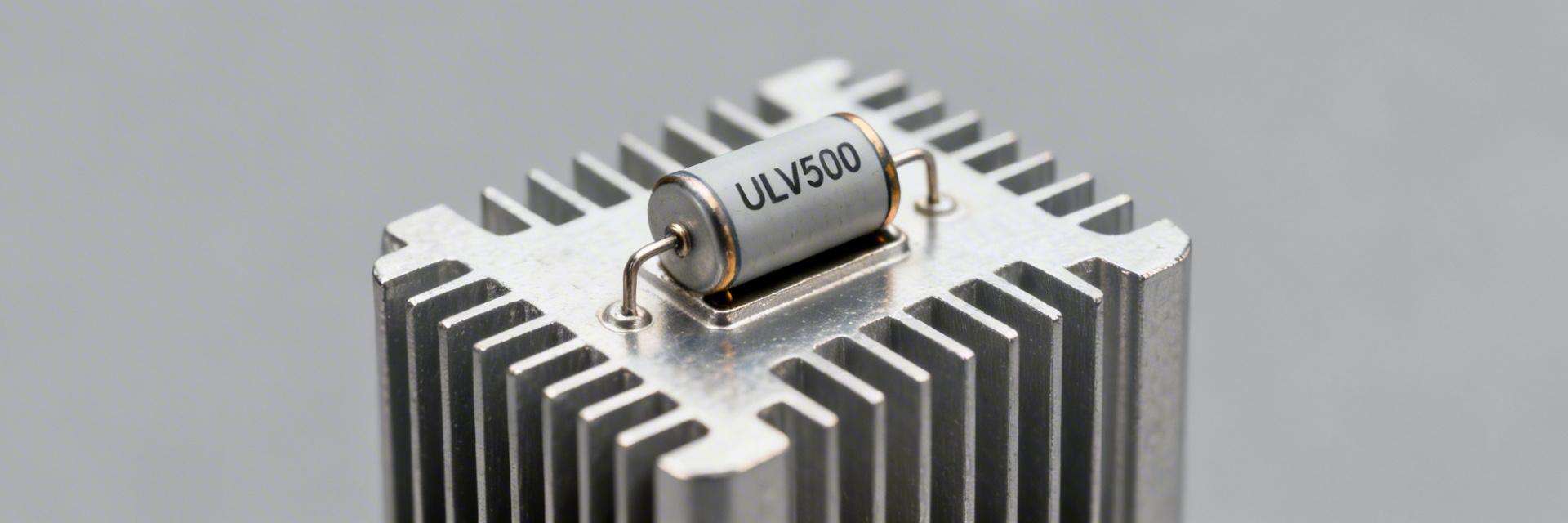
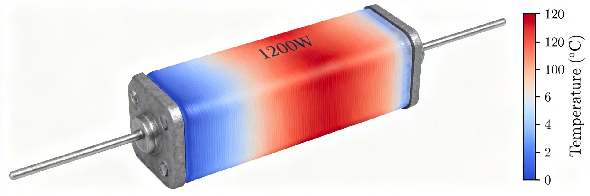
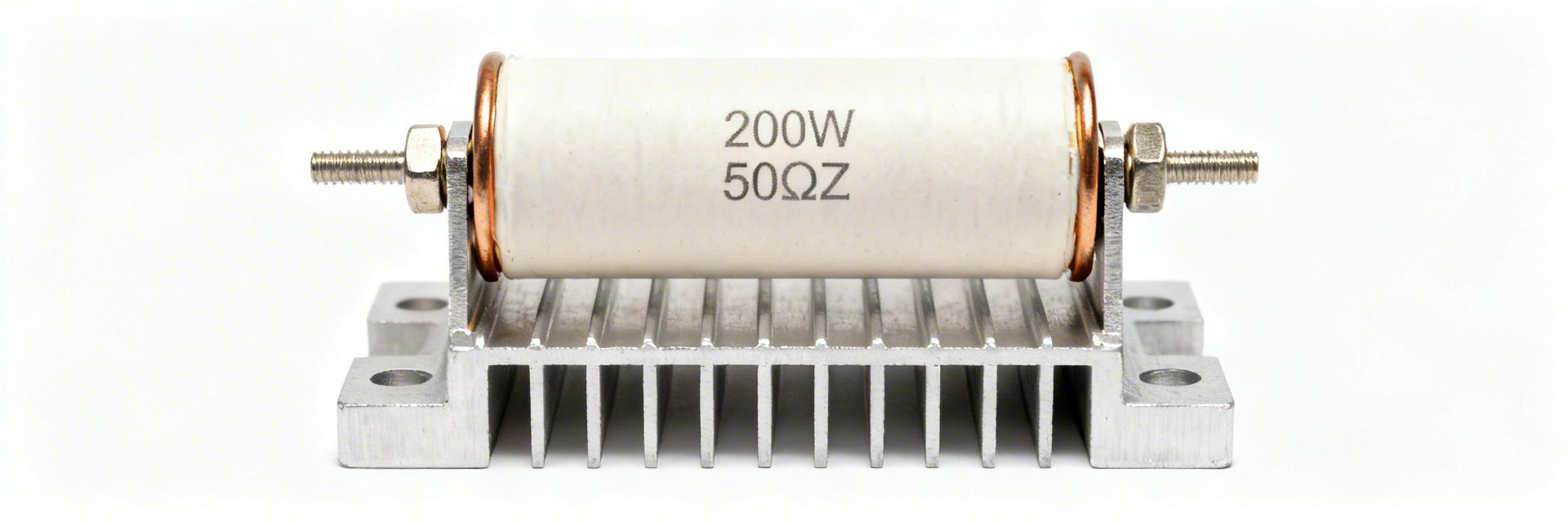
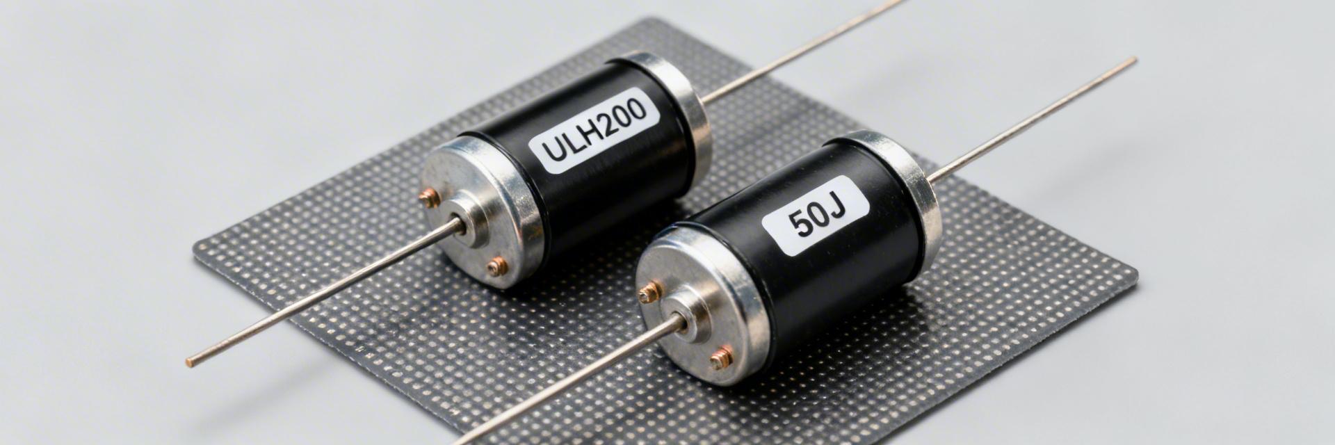
ULH 150 60 J resistor datasheet: Performance Deep Dive
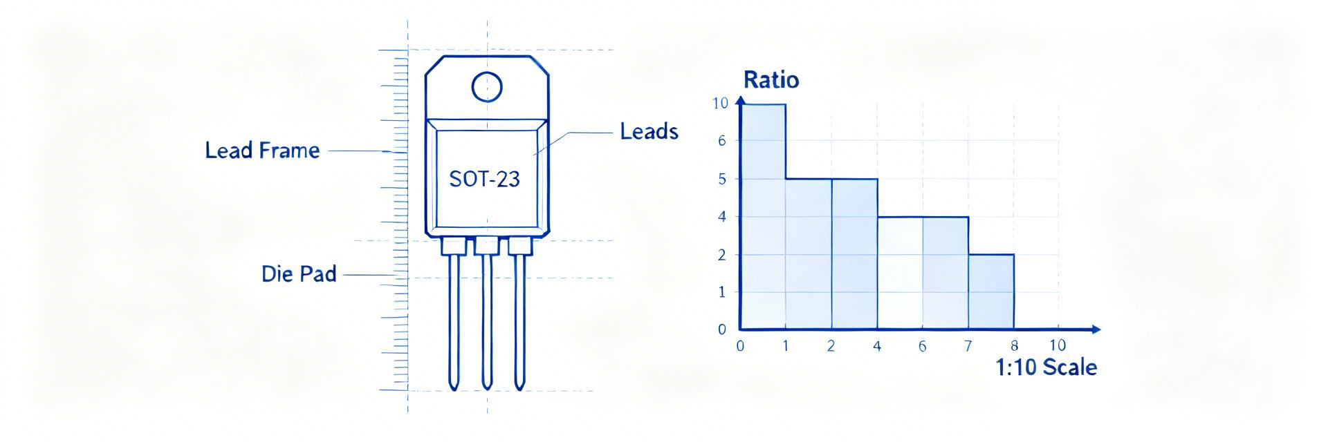
Key Takeaways (Core Insights) Max Power Density: Achieves 150W dissipation in a compact metal-clad footprint when heatsink-mounted. Thermal Derating: Critical 83% power drop (from 150W to 25W) when moving from heatsink to free-air cooling. Pulse Resilience: High thermal mass allows for significant short-term braking energy beyond continuous ratings. Precision Safety: ±5% (J) tolerance combined with 2.5kV insulation ensures reliable industrial safety margins. Introduction: Lab and datasheet figures for ULH-class metal-clad resistors routinely show peak continuous dissipation on a heatsink near 150 W and distinct derating below that in free air. This article breaks down the ULH 150 60 J resistor performance using key datasheet metrics so engineers can validate thermal limits, calculate real-world dissipation, and compare specification trade-offs. The datasheet context and measured performance figures guide selection and verification. Introduction: Point — engineers need clear rules to convert datasheet graphs into installation limits. Evidence — typical datasheet plots give heatsink-rated power, derating slope, and thermal resistance. Explanation — this article turns those plots into worked examples, checklists and quick calculations to reduce risk during procurement and commissioning. Product Overview & Key Specifications 150W Rated Power Enables 30% more power density compared to standard ceramic resistors, saving cabinet space. Metal-Clad Housing Provides superior vibration resistance and direct thermal conduction for harsh environments. 2.5kV Insulation Prevents arcing in high-voltage braking circuits, ensuring operator and equipment safety. Model Nomenclature and what “150 60 J” means Point — model identifiers encode power, resistance and tolerance. Evidence — “150” maps to a nominal 150 W continuous heatsink rating; “60” indicates 60 Ω; “J” denotes ±5% tolerance. Explanation — reading the model ID lets engineers quickly filter candidates by nominal dissipation and resistance range; confirm full spec fields in the resistor datasheet before final selection. Spec Typical Value (from datasheet) Rated power (heatsink)150 W Resistance60 Ω Tolerance±5% (J) Temperature coefficient (TCR)±100 ppm/°C Insulation voltage2.5 kV (typical) Max case temp350 °C (mount-dependent) Mounting styleMetal-clad, bolt-mounted Competitive Differentiation Metric ULH 150 60 J (Chassis) Standard Tubular Wirewound Advantage Power/Volume Ratio High (Heatsink dependent) Low (Air convection) ULH saves ~40% space Vibration Rating Excellent (Encapsulated) Moderate (Exposed wire) Reliability in mobile apps Thermal Response Fast (Conductive) Slow (Radiative) Better peak load handling Mechanical footprint, terminals & mounting considerations Point — mechanical details drive thermal performance. Evidence — datasheet dimensional drawings show baseplate area, hole pattern, and terminal spacing. Explanation — larger contact area and correct bolt torque reduce thermal resistance; insufficient clearance or small mounting pads force additional derating for safe operation. Performance Data Deep-Dive Power handling, derating curves & example calculations Point — rated 150 W on a heatsink drops with ambient temperature and free-air mounting. Evidence — typical derating curve starts at 150 W at 25 °C sink and decreases linearly. Explanation — use P = I²R and I = sqrt(P/R) to translate power to allowable current for 60 Ω. Case Allowed P Allowed I = sqrt(P/R) Heatsink-rated (25°C)150 W1.58 A Derated (75 W @ High Temp)75 W1.12 A Free air (no heatsink)25 W0.65 A ENGINEER'S INSIGHT "When deploying the ULH 150 in braking load banks, many designers overlook Contact Thermal Resistance. Even with a perfect heatsink, using low-quality thermal paste can increase junction temperatures by 15-20°C. I always recommend a high-conductivity silicone-based compound and verifying the mounting torque to exactly the datasheet's Nm specification to ensure the 150W rating is actually achievable." — Marcus V. Steiner, Senior Power Systems Engineer Thermal metrics: thermal resistance and steady-state behavior Point — thermal resistance (°C/W) converts dissipation to temperature rise. Evidence — datasheet lists Rth(case‑to‑sink). Explanation — with Rth 0.5 °C/W and 75 W dissipation, temperature rise = 37.5 °C. Add ambient to predict case temp and verify it stays below 350 °C max. Electrical Behavior & Transients Surge, pulse and transient performance Point — pulses permit short bursts above continuous power. Evidence — datasheets provide pulse energy curves. Explanation — compute pulse energy for braking (E ≈ I²·R·t) and compare to the withstand graph; include 20–50% safety margin. [Typical Heatsink Mounting Interface] Hand-drawn illustration, not a precise schematic Long-term reliability and common failure modes Point — failures most often follow thermal overstress. Evidence — coating specs and max case temp. Explanation — implement temperature cycling and insulation resistance checks to validate lifetime. Typical Applications & Selection Common use cases: braking resistors, load banks Point — ULH-class resistors suit intermittent high-energy applications. Evidence — application notes show braking events with high peak current but low duty cycle. Explanation — size resistor by computing average power over duty cycle and applying a 1.5x safety margin. Engineering Checklist for Procurement Rated Power: Heatsink vs Free Air verification? Derating Curve: Slope and reference ambient captured? Pulse Rating: Energy limits (J) for transient events? Resistance Tolerance: ±5% (J) acceptable for control loop? Mechanical: Mounting torque and clearance specs recorded? Summary The ULH 150 60 J resistor delivers high continuous dissipation when properly mounted and cooled, but safe deployment requires reading the resistor datasheet carefully — examining derating curves, thermal resistance, pulse ratings, and mechanical constraints — before final selection. Proper calculation and verification of dissipation and temperatures ensure reliable performance in braking and load applications. Frequently Asked Questions How do I size a ULH 150 60 J resistor for continuous braking? Calculate average regeneration power from motor current and duty cycle, then apply P = I²R to find resistor dissipation. Add 50% margin for safety and compare with the datasheet heatsink-rated power and derating curve. What is the pulse rating and how do I calculate pulse energy? Pulse ratings are provided as energy or I²·t limits. Compute pulse energy with E ≈ I²·R·t for short events, then ensure the single‑pulse energy and average power over repeated pulses remain within datasheet limits. How should I verify performance on receipt? Perform visual inspection, measure insulation resistance, confirm resistance at reference temperature, and run a low‑power soak test while monitoring case temperature.