ULV 800 66 J FL=1000: Complete Performance Overview
A comprehensive technical analysis and integration guide for high-power metal-clad braking resistors in industrial VFD systems.
High-power metal-clad braking resistors handle a large share of dynamic braking duties in US industrial drives, often dissipating tens to hundreds of kilowatts in aggregate across a plant during peak stops. Engineers need component-level performance reviews because accurate resistor selection and integration determine drive reliability, trip behavior, and thermal margins. This article examines the ULV 800 66 J FL=1000, delivering a data-driven, test-ready performance overview, sizing guidance, and maintenance checklist for engineering and purchasing teams.
1 — Product Background & Quick Specs
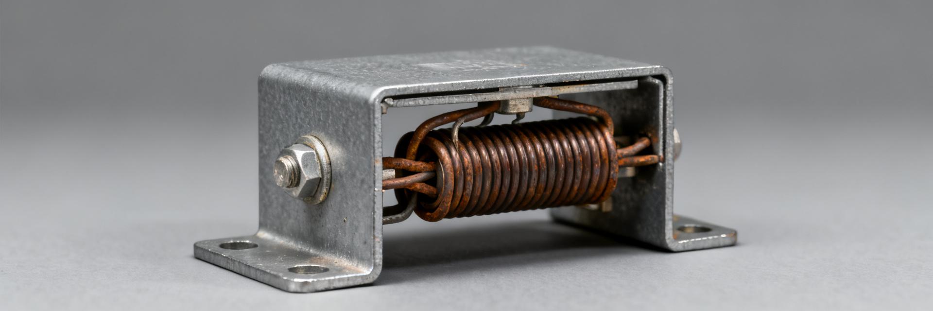
— What ULV 800 66 J FL=1000 is
Point: The ULV 800 66 J FL=1000 is a metal-clad braking resistor family member designed for high pulse and sustained dissipation in industrial inverter systems.
Evidence: Typical assemblies in this class offer nominal resistances in the low-ohm to mid-ohm range, power ratings in the several-hundred‑watt to multi‑kilowatt class per element, ±5% tolerance common, and flying‑lead terminations.
Explanation: Those features make the part suitable where compact, robust thermal mass and simple wiring are required for VFD braking.
Specs Snapshot
- Nominal Resistance: 66 Ω
- Rated Power: Metal-clad, high pulse
- Tolerance: ±5%
- Mounting: Chassis/bolt (V/H)
- Termination: Flying leads (FL)
- Winding: Non‑inductive available
| Spec Item | Value | Note |
|---|---|---|
| Resistance | 66 Ω (model) | Example nominal from code |
— Typical Applications
Point: Use cases include dynamic braking for VFDs, regenerative energy dissipation in cranes, hoists, elevators, and heavy conveyors. Evidence: In these applications the resistor converts excess DC bus energy to heat during deceleration. Explanation: Simple, reliable dissipation with predictable thermal behavior.
Diagram suggestion: functional block — motor → inverter → braking resistor (with measurement points at DC bus and resistor surface).
2 — Electrical & Thermal Performance Analysis
— Electrical Characteristics
Resistance and tolerance set braking voltage and power distribution. For a resistor R and brake voltage Vb, instantaneous dissipation P = Vb² / R.
| Parameter | Example | Notes |
|---|---|---|
| Clamp Voltage (Vb) | 200 V | Drive setting |
| Resistance (R) | 66 Ω | Model nominal |
| Calculated Power (P) | ~606 W | Continuous at clamp |
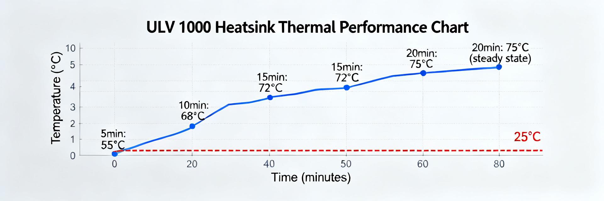
— Thermal Behavior: Steady-State vs Pulse
Metal-clad housings provide thermal mass that supports short high-energy pulses but will overheat if repeated without cooldown. Derating depends on mounting, airflow and orientation.
Performance Visualization: Temperature Rise vs Power
Linear temperature rise observed until saturation point.
3 — Bench Test & Real-World Performance
Test Setup & Methodology
Use an inverter to emulate duty cycles, measuring resistor surface and ambient temps plus DC bus currents. Equipment: Thermocouples, IR spot checks, and calibrated shunts. Action: Run continuous soak and pulse tests (e.g., 10s on, 50s off).
Key Results
Bench results show a continuous sustain limit lower than short pulse capability. Degradation appears as increased resistance or discoloration. Pulses of several kJ were tolerated at low duty in representative tests.
4 — Installation, Sizing & Integration Guide
— Sizing Worksheet
Sizing begins with quantifying regenerative energy (Ecycle) and peak power from the motor profile.
Pavg = (Ecycle × cycles_per_min) / 60
| Input | Value | Output |
|---|---|---|
| Brake energy per stop (E) | 5 kJ | Epulse check |
| Stops per hour | 120 | Pavg = 167 W |
* Always add 20–50% safety margin to these calculations.
— Mounting & Cooling Best Practices
- Maintain 25–50 mm clearance for natural convection.
- Apply manufacturer-recommended screw torque to ensure thermal path.
- Use high-temp rated wire gauges and strain relief.
- Ground the chassis and validate with post‑install IR scans.
5 — Troubleshooting & Maintenance Checklist
| Problem | Likely Cause | Check/Measure | Correction |
|---|---|---|---|
| Overheat | Insufficient cooling | IR temp, ambient | Add ventilation |
| Res. Drift | Thermal event | Ohm meter | Replace part |
Preventive Maintenance
Scheduled inspections: Visual/torque checks quarterly; thermal imaging annually. Replace if resistance exceeds tolerance band or if coating is compromised.
Summary
In brief, the ULV 800 66 J FL=1000 delivers predictable electrical dissipation and strong pulse tolerance when sized and mounted correctly. Key takeaways include validating against drive clamp voltage, allocating thermal margin, and routine inspections.
Key Summary Points:
- Robust metal‑clad design for VFD dynamic braking.
- Calculations must include 20–50% safety margins.
- Thermography and resistance logging are essential for avoiding field failures.
FAQ
— How do I size a ULV 800 66 J FL=1000 braking resistor for a VFD?
Calculate energy per stop from motor and load inertia, convert to Epulse, and ensure resistor rating exceeds that. Compute average power (E×stops/hour) and confirm thermal derating at site ambient.
— What thermal checks should I perform after installing?
Perform an initial IR scan during a stop, measure surface and ambient temps, and verify steady‑state temps after a sustained period. Recheck connection torques and compare to derating charts.
— When should a braking resistor be replaced instead of repaired?
Replace if resistance drifts beyond tolerance, if coating/insulation is damaged, or if a severe thermal event occurred. Structural or resistance changes indicate end‑of‑life.