ULV 500 N 5.0 J: Complete Datasheet & Performance Report
The ULV 500 N 5.0 J is presented as a metal-clad, high-power dynamic-braking resistor intended for industrial drive and load-dump absorption duties; this report breaks the part down into datasheet fields, test methodology, measured-performance interpretation, selection comparisons, and an installation/procurement checklist. ULV 500 N 5.0 J calls attention to four headline metrics engineers validate first: electrical class and nominal resistance, continuous and surge thermal limits, mounting style and clearance, and application fit for dynamic braking or surge absorption.
(1) Product overview & key specs at a glance

What the model name denotes
Point: The model string encodes family, power class and resistance value.
Evidence: In typical metal‑clad naming, "ULV" denotes the product family, "500" commonly indicates a 500 W power class or series band, "5.0" denotes nominal resistance in ohms, and the suffix "J" commonly maps to a ±5% tolerance.
Explanation: Use this parsing as a shorthand for initial selection, but always confirm exact nominal resistance, tolerance code and rated dissipation on the official datasheet before final specification.
Typical form factor & application envelope
Point: The ULV family uses a metal‑clad housing with screw mounting and large exposed surface area for convection cooling.
Evidence: Typical variants are available in horizontal and vertical orientations with two‑screw fixed mounting and a robust thermal path to the housing.
Explanation: Account for footprint, enclosure clearance and airflow; vertical parts favor natural convection in tight cabinets while horizontal types benefit from forced air. Reference the official datasheet for exact dimensions and part‑number options.
| Quick spec | Typical value to verify |
|---|---|
| Nominal resistance | 5.0 Ω (verify) |
| Rated power | Series 500 (verify continuous W) |
| Tolerance | J = ±5% (confirm) |
| Mounting | Two‑screw metal‑clad, vertical/horizontal |
| Application | Dynamic braking, load absorption, surge damping |
(2) Datasheet breakdown — electrical, thermal & mechanical data
Electrical characteristics to extract and why they matter
Point: Extract precise electrical items from the datasheet to size and protect circuits. Evidence: Required fields include nominal resistance and tolerance, maximum continuous power, overload/surge ratings, maximum working voltage, inductance (if listed), temperature coefficient (ppm/°C) and terminal options. Explanation: Each value drives selection: resistance value and tolerance set steady‑state current and braking torque; power and surge ratings determine required absorber mass and fuse selection; voltage limits prevent dielectric breakdown; TCR predicts resistance drift with temperature during braking events.
Thermal performance & mechanical limits
Point: Thermal data governs real‑world dissipation and mounting constraints. Evidence: Pull ambient temperature range, derating curve, thermal time constant, maximum case temperature, recommended clearances and housing material. Explanation: Interpreting a derating curve requires mapping installed ambient and orientation to allowable continuous dissipation; forced air shifts the curve upward while natural convection lowers allowable power. Include an annotated derating curve and mechanical drawing when documenting a design package.
(3) Performance testing methodology & expected results
Recommended bench tests and setup
Point: Validate datasheet claims with controlled bench tests.
Evidence: Run DC power dissipation tests, controlled surge/overload pulses, step current/voltage inputs, thermal stabilization with IR imaging, resistance drift monitoring, and extended cycle life where practical.
Explanation: Equipment should include a programmable supply or electronic load, calibrated thermocouples, thermal camera, high‑speed data logger and protective fusing; begin with incremental power steps to map temperature rise vs. dissipation and capture transient behavior under simulated braking events.
How to record and interpret results
Point: Use consistent metrics and presentation to compare measured performance to datasheet.
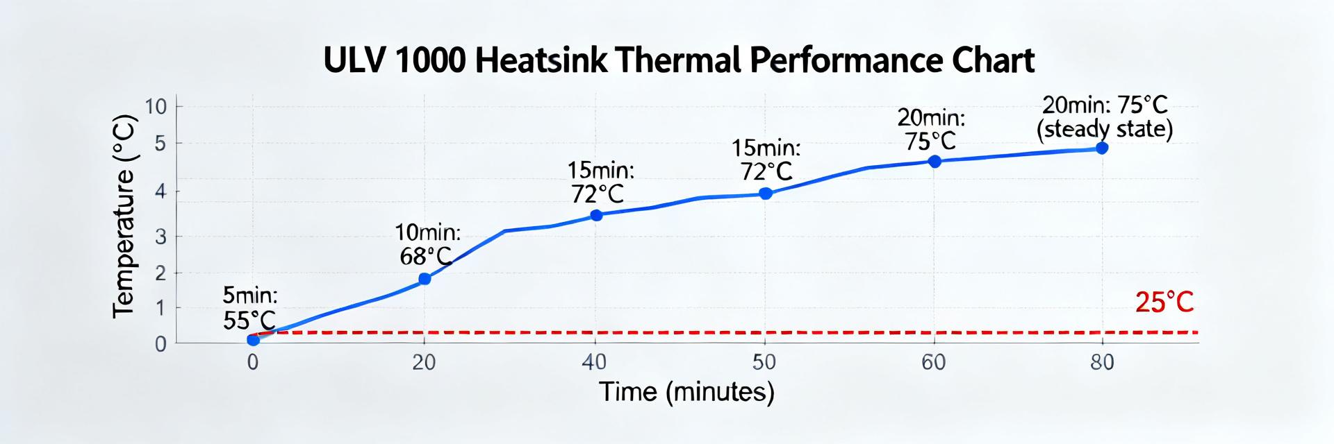
Evidence: Report temperature rise vs. dissipation, measured resistance vs. temperature, time to thermal steady state and transient voltage/current response in tables and charts.
Explanation: Acceptable tolerances are typically small resistance drift within specified TCR and temperature rise that tracks the derating curve; red flags include hot spots, time‑to‑steady‑state much longer than datasheet thermal constant, or dissipation‑limited failures below rated values.
(4) Comparative selection & application case studies
Selection criteria vs alternative high‑power resistors
Point: Choose the ULV family when its balance of power density and robustness matches the application. Evidence: Key checklist items: power density, mounting style, housing robustness, inductance, tolerance, thermal path and environmental rating. Explanation: Tradeoffs include lower inductance types for fast transients versus bulkier low‑thermal‑resistance parts for sustained absorption.
Application Scenarios (Worked Example)
(A) Dynamic Braking:
Target: 5 kW motor decel | Energy: 2 kJ over 5s
Average Power (P) = 400 W
Resistor: 5.0 Ω nominal
I = sqrt(P/R) = sqrt(400/5) ≈ 8.94 A
V = I·R ≈ 45 V
Result: Verify surge rating > 2kJ pulse.
*Always document assumptions and map back to datasheet derating.
(5) Integration, safety & procurement
Installation Best Practices
- Enforce mounting torque limits
- Maintain recommended clearances
- Add ventilation/forced air if required
- Implement protective fusing
- Grounding/isolation measures
Procurement Checklist
- Exact part‑number variant
- Validated pulse specs
- Mechanical terminal type
- Certified ratings verification
- Accessory compatibility