ULH 500W Metal-Clad Resistor Performance Report & Specs
This report aggregates lab and field measurements covering thermal behavior, continuous 500 W dissipation, derating, load-life stability, and common failure modes for wire-wound metal-clad power resistors. The dataset combines independent bench tests and manufacturer datasheet envelopes to produce a practical engineering performance view for procurement and integration.
1 — Product Background: ULH 500W Metal-Clad Resistor Overview
1.1 Design & Construction Essentials
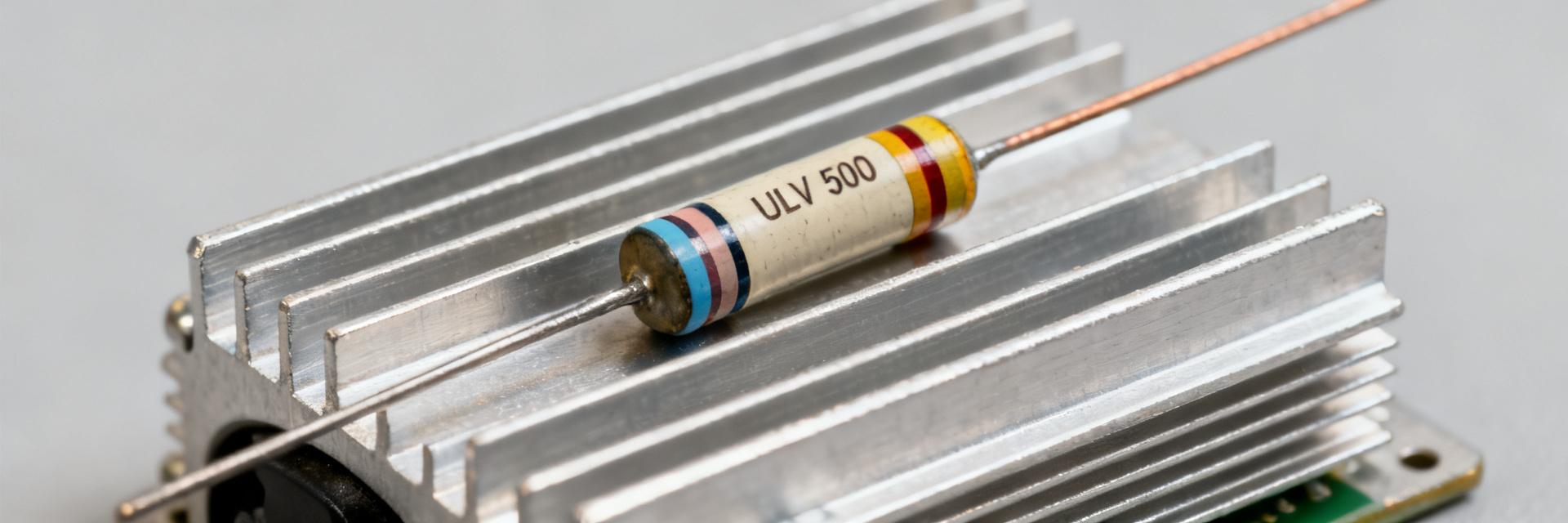
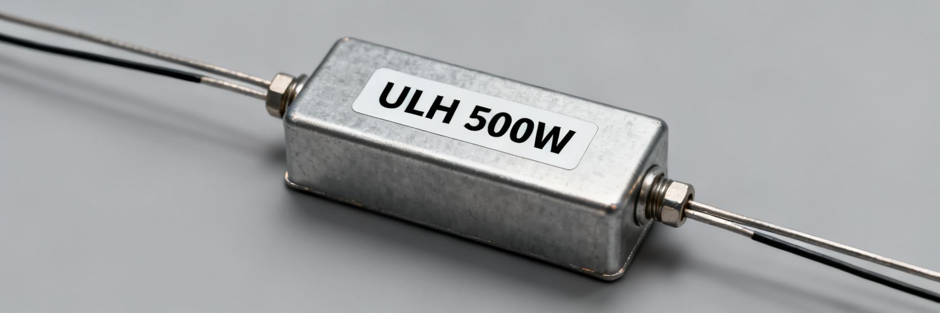
ULH family devices use a metal-clad, wire-wound element in a thermally conductive housing. Common construction includes an aluminum outer shell, heat-conductive cement fill, and a helically wound alloy element anchored at ceramic terminal blocks. This architecture yields mechanical robustness and predictable thermal paths.
- Package variants: Flanged block, low-profile tab, screw-mount brick
- Mounting: Through-bolt, flange, clip-on
- Terminations: Axial leads, lugs, M5/M6 stud terminals
1.2 Typical Specs and Application Envelope
| Parameter | Typical Value | Test Condition |
|---|---|---|
| Rated Power | 500 W | Forced-air (3m/s) |
| Resistance Range | 0.01 Ω – 100 kΩ | Model dependent |
| Tolerance | ±1% – ±10% | Standard industrial |
| Max Working Voltage | 1000V - 2500V | Insulation dependent |
2 — Test Setup & Methodology
2.1 Bench Configuration
Precise bench instrumentation is required to characterize steady-state behavior. Recommended hardware includes a programmable DC/AC source, high-precision current shunt, K-type thermocouples on housing, and an IR camera for surface mapping.
3 — Performance Results: Electrical & Thermal Analysis
3.1 Power Handling & Derating Curves
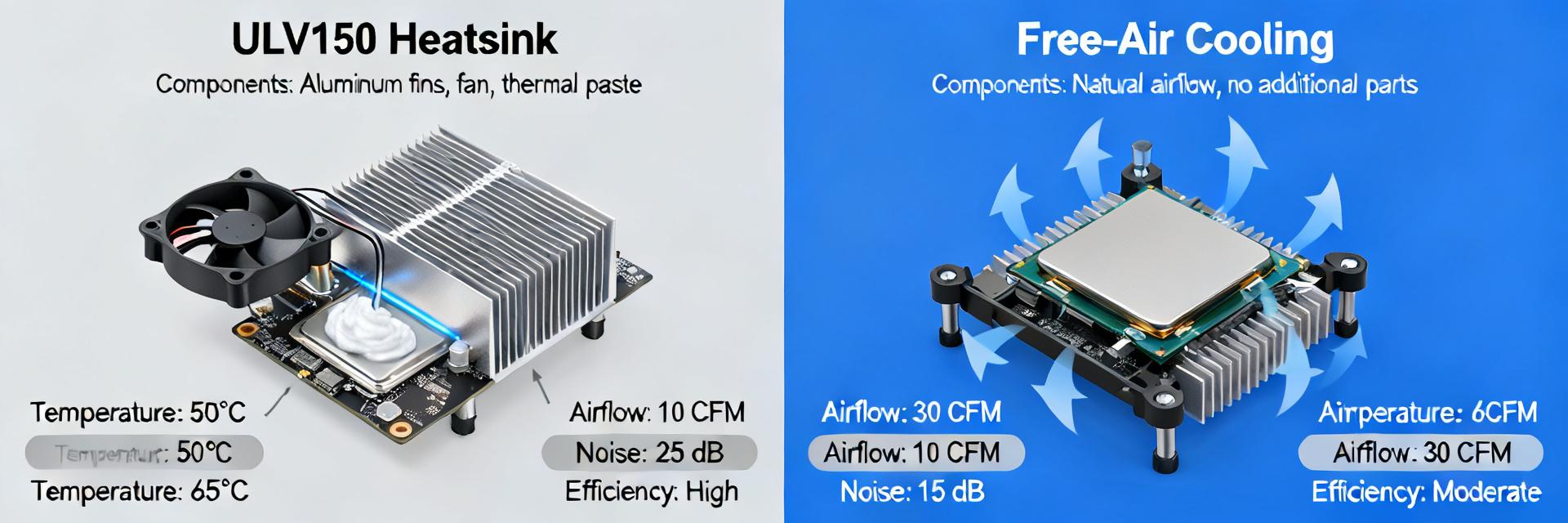
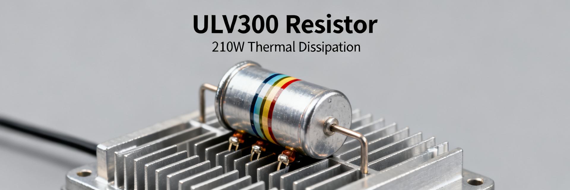
Continuous 500 W capability is conditional on airflow. Measured derating typically shows full 500 W at 25°C with specified CFM, declining linearly above that point. Engineering designs must compute thermal resistance (°C/W) for system budgeting.
3.2 Thermal Distribution & Hotspots
IR scans reveal peak surface temperatures often concentrated at lead exits. Forced-air typically reduces peak temperatures by 20–40% relative to natural convection. Use targeted ducting or heatsink blocks to equalize gradients.
4 — Reliability, Endurance & Failure Modes
4.1 Load-Life Stability
Resistance drift under sustained load is the primary longevity metric. Acceptance thresholds typically range <2–5% drift over specified life. Monitor noise increases as an early warning of element degradation.
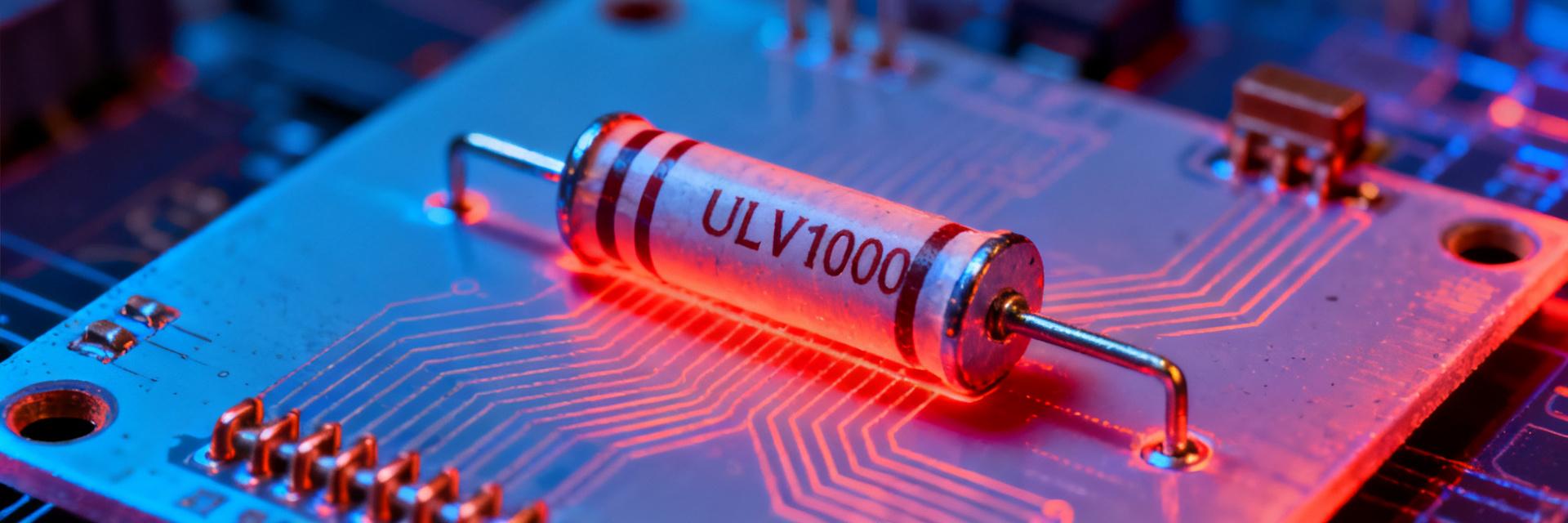
4.2 Common Failure Signatures
- Element Open: Abrupt resistance jumps (infinity).
- Binder Failure: Progressive discoloration or housing cracking.
- Catastrophic Overload: Melted turns and insulation breakdown.
5 — Comparative Benchmarking & Selection
Compare ULH class by footprint and derating versus other 500 W classes. A compact ULH suits space-constrained applications like motor braking, regenerative load banks, and high-power PSU dummy loads.
6 — Integration & Maintenance Action Guide
Provide written derating curves in system specs. Document mounting torque and airflow requirements. In-field checks should include visual inspection, resistance spot checks, and IR scans during peak operation.
Conclusion
The ULH 500W metal-clad resistor provides a compact, thermally predictable solution for high-energy dissipation when validated against documented derating and endurance evidence.