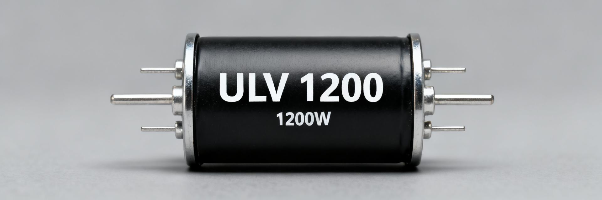
ULV 300 resistor: Free-air 210W & thermal performance data
The ULV 300 resistor is commonly specified at 300 W when mounted to a heatsink and approximately 210W free-air under published test conditions. This technical briefing focuses on interpreting these metrics for power-electronics thermal design. For engineers, translating these headline ratings into real-world allowable dissipation requires a deep dive into thermal resistance (Rth), ambient constraints, and steady-state validation.
1 — Technical Overview: ULV 300 Essentials
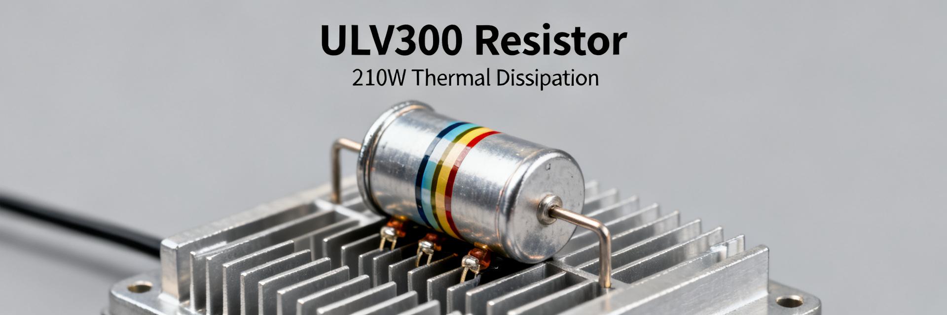
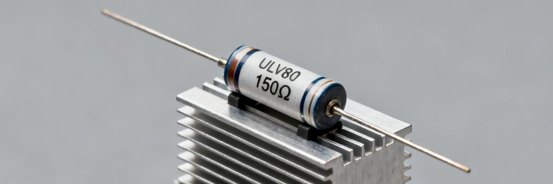
Understanding the form factor is the baseline for thermal contact. ULV 300 resistors typically feature metal-clad construction designed for high energy absorption and efficient heat transfer.
1.1 Mechanical and Electrical Limits
| Parameter | Typical Value | Test Condition |
|---|---|---|
| Rated Power (Heatsink) | 300 W | Standard Al-Heatsink |
| Rated Power (Free-Air) | ~210 W | Vertical orientation, 25°C |
| Operating Case Tmax | Datasheet specific | Manufacturer limit |
1.2 Defining the "210W Free-Air" Benchmark
The free-air rating indicates the power the component can sustain without external cooling. However, factors like proximity to other components or enclosure air stagnation will significantly reduce this sustainable power level.
2 — Thermal Metrics & Rth Extraction
To convert published data into design limits, engineers must utilize thermal arithmetic. The relationship between power (P), thermal resistance (Rth), and temperature rise (ΔT) is the foundation of safe operation.
| Thermal Metric | Unit | Typical Use |
|---|---|---|
| Rth (case-to-ambient) | °C/W | ΔT = P × Rth |
| Delta T at Rated P | °C | Sanity Check |
| Time Constant (τ) | s–min | Steady-state timing |
3 — System Design & Braking Case Study
Consider a braking resistor in a drive system dissipating 180W continuous in a 40°C ambient. If the Rth is 0.33°C/W, the calculated case temperature would be ~99.4°C. This must be compared against the datasheet Tmax to determine if a heatsink is mandatory.
| Scenario | Required | Result |
|---|---|---|
| Continuous Dissipation | 180 W | Tcase ≈ 99.4 °C |
| Published Free-Air Limit | ~210 W | ~15% Design Margin |
4 — Validation & Lab Test Methods
Validation involves instrumenting the resistor at the geometric center of its case. Tests should run until the temperature plateau is reached (10–30 mins). Use thermal imaging to identify hotspots that might not be captured by point-contact thermocouples.
5 — Practical Design Checklist
- Verify Rth: Confirm the manufacturer’s test setup matches your mounting.
- Calculate Limits: Use
P_allowed = (Tcase_max − Tambient) / Rth. - Apply Margin: Standard industrial practice suggests 10–30% derating.
- Monitor: Implement thermal cutouts for mission-critical power paths.
FAQ
What is the ULV 300 resistor free-air rating and how conservative is it?
How do I use Rth to check the ULV 300 resistor for my application?
DeltaT = Power × Rth. Add this to your maximum local ambient to ensure the total case temperature remains below the component's rated maximum.