


Helping you save cost and time.

Provide reliable packaging for your goods.

Quick and reliable delivery to save time.

Excellent after-sales service.
New Product Launch
More +


Hot Selling Parts


Blog
HoFL3-8518-A-50uR-1% Complete Specs, Test Data & Sourcing
Point: By consolidating datasheets, independent lab reports, and field logs, procurement and engineering teams can form a verified performance envelope for the HoFL3-8518-A-50uR-1%. Evidence: Aggregat…
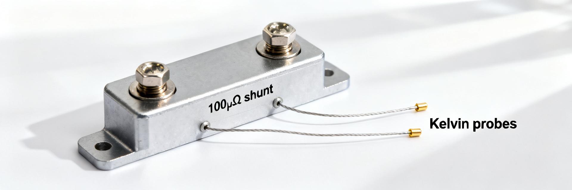
100µΩ Shunt Resistor Report: Precision Specs & Test Data
Demand for sub‑milliohm current sensing has risen sharply in high‑power battery systems and power conversion equipment; designs increasingly require 100µΩ shunt resistor measurements with millivolt‑le…
AD45336KSTZ: Latest Performance Report & Key Specs
2026-07-01 11:25:16
AD45336 Datasheet Deep Dive: Specs, Pinout & Analysis
2026-06-29 10:16:15
MIUZ100R12GJTL-BP Thermal Report: Key Performance Data
2026-06-28 14:46:16
STGWA30IH160DF2: Power & Key Electrical Specs Report
2026-06-27 10:15:24
NXH600N105L7F5S1HG performance report: Specs & Metrics
2026-06-26 10:16:24
Read more