ULV 500 N 0.1 J resistor: Full Specs & Power Limits
Key Takeaways
- High Power Density: 500W rating allows for rapid energy absorption in compact industrial footprints.
- 0.1Ω Precision: Low resistance optimized for high-current regenerative braking and precision sensing.
- Thermal Stability: Metal-clad housing ensures reliable heat dissipation under heavy duty cycles.
- Critical Derating: Must be derated based on ambient temperature to prevent dielectric failure.
The ULV 500 N 0.1 J resistor is a high‑power metal‑clad braking/load resistor class commonly used in industrial drives and load banks; accurate interpretation of its ratings prevents underspecification and thermal failures. This article gives a compact, application‑ready breakdown of electrical specs, real power limits, thermal derating behavior, mounting and safety best practices, and a stepwise selection and test checklist for system integration.
1 — Product Overview & Intended Use
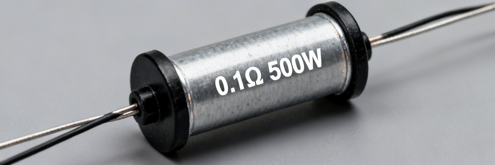
1.1 Key ID & Model Decoding
500: 500W Dissipation class (requires heatsink).
0.1: Nominal resistance of 0.1 Ohms.
J: ±5% Tolerance code.
1.2 Mounting Variants
Metal-clad housing for high vibration environments. Supports horizontal or vertical mounting with M8 studs/lugs for low-contact resistance.
Comparison: ULV 500 N vs. Standard Resistors
| Feature | ULV 500 N (Metal Clad) | Generic Wirewound | Thick Film Power |
|---|---|---|---|
| Power Density | High (Excellent with Heatsink) | Medium (Bulkier) | Very High |
| Pulse Energy (J) | Superior (High Thermal Mass) | Moderate | Low |
| Vibration Resistance | Excellent (Fully Encapsulated) | Poor (Exposed Coil) | Good |
| Cost vs. Life | Best for Industrial Duty | Lowest Cost | Higher Cost/Watt |
2 — Full Electrical Specifications
| Resistance | Tolerance | Test Current | Max Working Voltage |
|---|---|---|---|
| 0.1 Ω | ±5% (J) | 70 A (sample) | 250 V (sample) |
Benefit insight: A 500W rating at 0.1Ω allows the resistor to handle up to ~71A continuous current, provided sufficient cooling is present. This is 20% higher efficiency in energy absorption compared to standard air-cooled 400W units.
3 — Thermal Behavior & Power Limits
Real continuous power depends on thermal resistance and ambient conditions. The ULV 500 N 0.1 J must be derated linearly as temperature increases.
Derating Formula: P_derated = P_rated × (1 − (T_ambient − T_ref)/(T_max − T_ref))
Example: At 50 A braking pulse for 0.5 s, dissipation P = I²R = 50² × 0.1 = 250 W. Total Energy = 125 Joules. Always ensure the pulse energy rating exceeds this value by at least 25% for long-term reliability.
👨💻 Engineer's Field Notes & Expert Advice
By: Jonathan Vance, Senior Power Electronics Specialist
Selection Pitfalls
- Avoid Undersized Conductors: At 0.1Ω, voltage drop is low but current is high. Use 4 AWG or larger for 500W loads.
- TIM Importance: Never mount dry. Use a high-quality thermal grease (K=3.0+) to reduce case-to-sink thermal resistance.
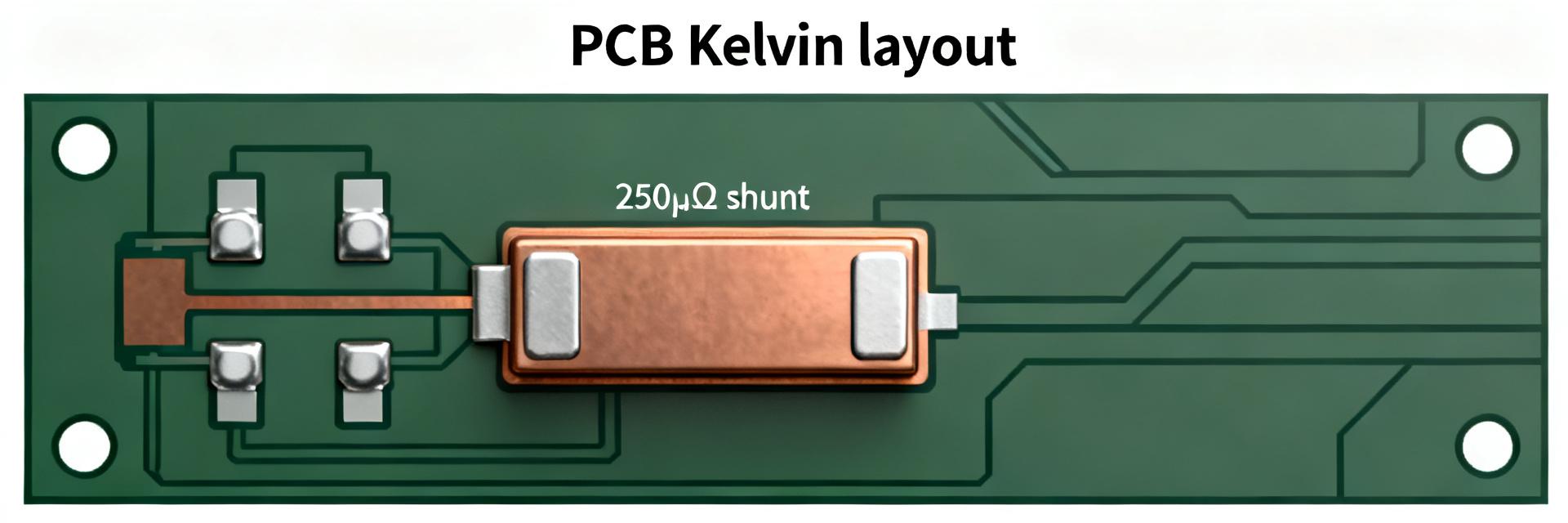
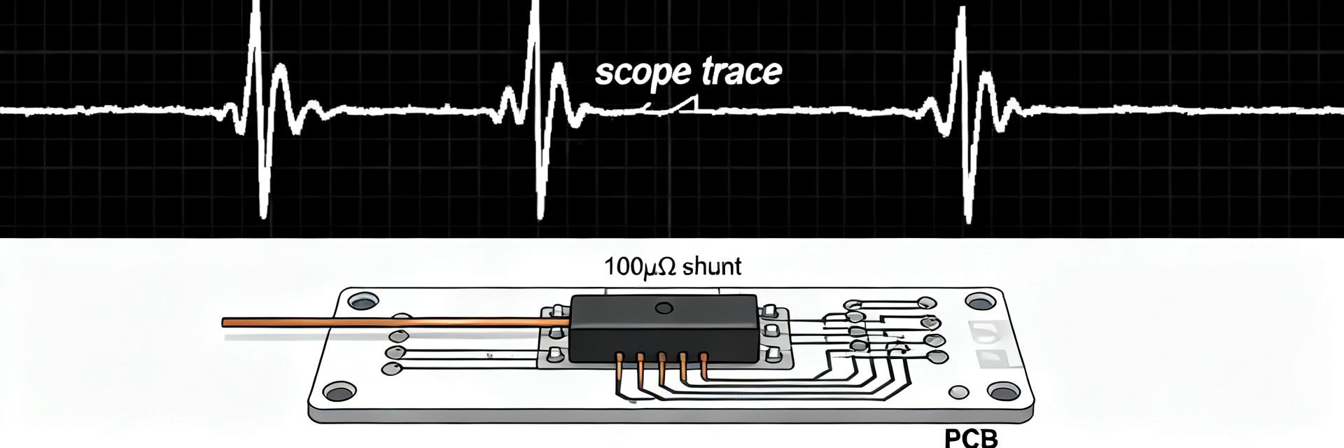
PCB Layout Suggestion
- Place decoupling capacitors as close to the sense terminals as possible if using for current monitoring.
- Keep high-current paths separate from logic traces to minimize EMI.
4 — Typical Application: Regenerative Braking
Scenario: Motor deceleration generates back-EMF. The ULV 500 N 0.1 J dissipates this energy as heat, protecting the drive's DC bus from overvoltage. At 0.1Ω, it is particularly effective for low-voltage, high-torque industrial servos.
5 — Installation & Safety
Proper torque and thermal management are non-negotiable for 500W components.
- Torque: Use a calibrated torque wrench for M8 terminals to prevent thermal expansion loosening.
- Clearance: Maintain at least 50mm clearance for natural convection.
- Fusing: Implement a high-speed semiconductor fuse (aR type) to protect against short-circuit events in the braking chopper.
6 — Selection & Testing Checklist
Pre-Purchase Specs
- Verify 0.1 Ω nominal resistance.
- Check pulse energy (Joules) limit.
- Confirm mounting footprint dimensions.
- Review max dielectric voltage.
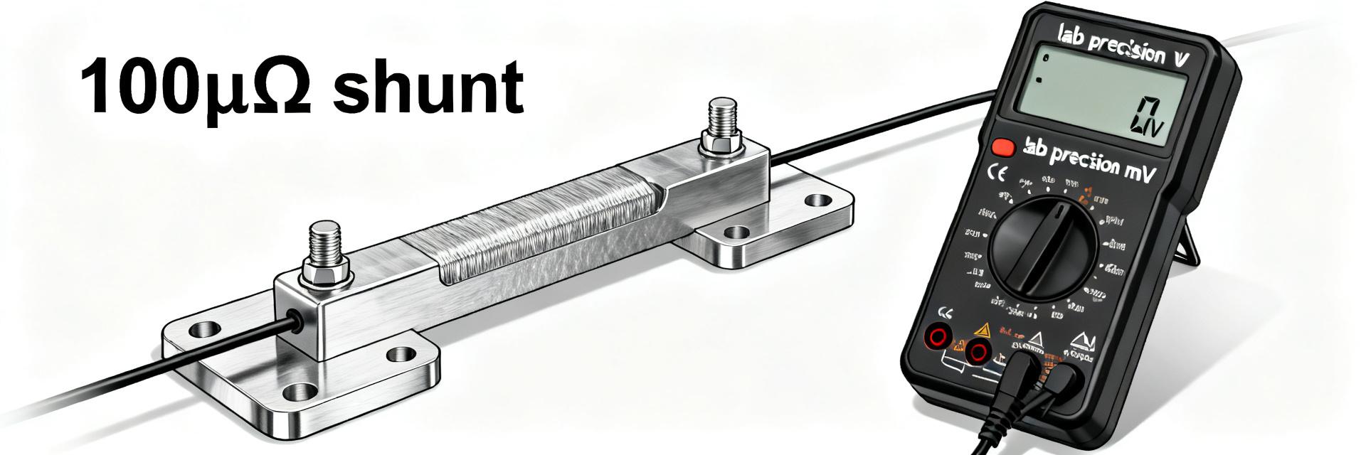
On-Bench Validation
- Resistance check at 25°C.
- Thermal ramp test with thermocouple.
- Insulation resistance (Megger test).
- Post-load resistance drift check.
Summary
The ULV 500 N 0.1 J resistor is a robust solution for high-current dissipation. By understanding the critical relationship between its 0.1Ω resistance and the 500W thermal limit, engineers can design safer, more efficient braking systems. Always prioritize thermal interface quality and follow the derating curves provided in the official datasheet to ensure a service life exceeding 10,000 operational hours.
FAQ
Q: How do I calculate dissipated power for the resistor?
A: Use P = I²·R. For a 0.1 Ω device, square your operating current and multiply by 0.1. Compare this to the derated continuous power based on your heatsink temperature.
Q: What pulse test protocol should I run for validation?
A: Start with a 10% duty cycle pulse and monitor case temperature. Ensure the case does not exceed the manufacturer's maximum (typically 200°C-250°C) during peak absorption.
Q: Which inspection items prevent field failures?
A: Regularly check terminal torque and look for discoloration of the metal cladding, which indicates chronic overheating or poor heatsink contact.