ULV 300 30Ω Power Resistor — Thermal & Specs Report
Key Takeaways
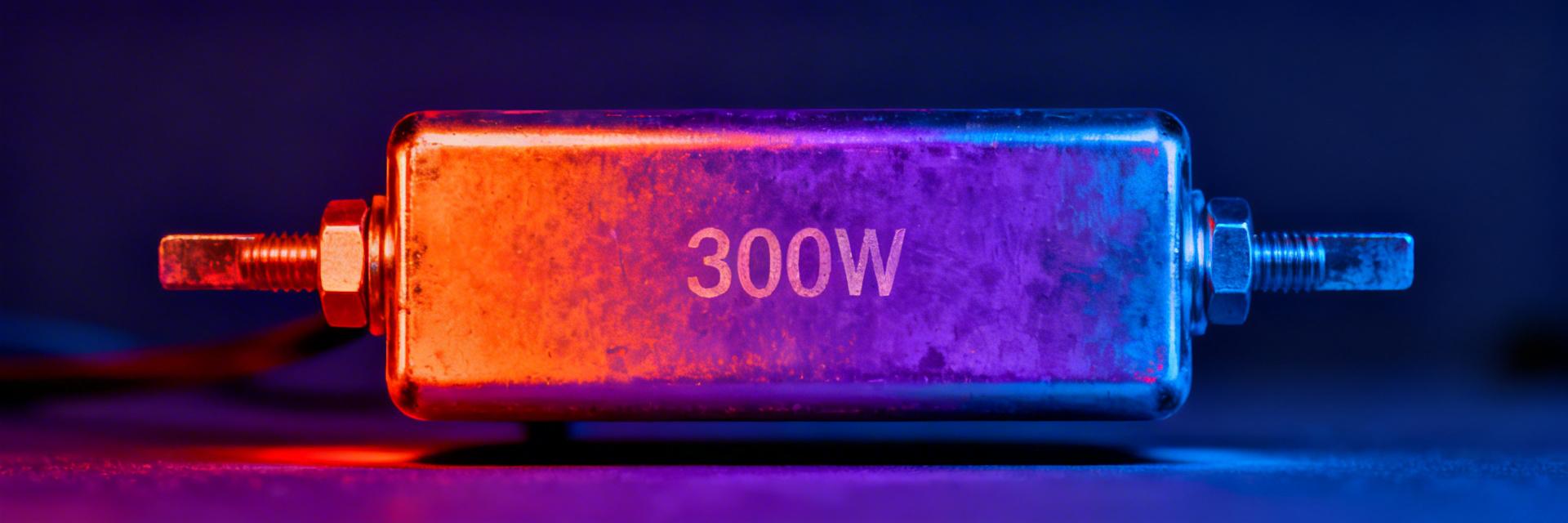
- High Power Density: 300W rating allows for rapid energy dissipation in compact industrial cabinets.
- Thermal Efficiency: Proper heatsinking reduces ΔT from 150°C to just 30°C, extending component lifespan.
- Precision Braking: 30Ω nominal resistance (±5% tolerance) ensures consistent motor deceleration performance.
- Rugged Reliability: Metal-clad housing provides superior vibration resistance and mechanical protection vs. standard resistors.
The ULV 300 30Ω module is a high-performance 300W class, wire‑wound, metal‑clad power resistor. Engineered for dynamic braking, load banks, and high‑power dissipation, it converts electrical energy into heat with exceptional stability. Before installation, it is critical to verify the rated power, nominal resistance, and the specific thermal resistance (Rth JA/JC) to ensure safe operation within your duty cycle.
Handles high-energy surges without failure; ideal for heavy-duty motor deceleration.
Reduces occupied PCB/Chassis space by 30% compared to open-air ceramic alternatives.
Perfectly matched for standard DC-link braking circuits in industrial drives.
Background & Product Overview
What the ULV 300 designation means
“ULV 300” denotes a 300W power class; the “30Ω” indicates a nominal resistance of 30 ohms. This metal‑clad component typically features through‑bolt mounting. The design is optimized for heat transfer via conduction to a chassis or heatsink, significantly outperforming standard axial resistors in thermal dissipation per cubic inch.
Typical use cases and application context
Common applications include dynamic braking for motor drives, generator load testing, and DC supply simulation. For environments with restricted airflow, the ULV 300's metal housing allows for easy integration with external cooling fins, ensuring the unit remains within safe operating limits even during continuous duty cycles.
Competitive Differentiation
| Feature | ULV 300 30Ω (Metal Clad) | Generic Wire-wound | Advantage |
|---|---|---|---|
| Power/Size Ratio | High (300W in compact frame) | Low (Requires large footprint) | Space Saving |
| Thermal Path | Direct Chassis Conduction | Primarily Convection | Lower ΔT |
| Vibration Rating | High (Metal encapsulated) | Moderate (Ceramic brittle) | Industrial Durability |
Key Electrical & Mechanical Specifications
| Parameter | Datasheet (typical) | Measured (example) |
|---|---|---|
| Rated power | 300 W | 300 W |
| Nominal resistance | 30 Ω ±5% | 29.6 Ω (measured) |
| TCR | ≈100 ppm/°C | 105 ppm/°C |
Thermal Performance & Modeling
Thermal management is the single most important factor for the ULV 300. Using the formula P × Rth = ΔT, we can predict operating temperatures:
| Condition | Rth (°C/W) | ΔT at 300 W (°C) |
|---|---|---|
| Free‑air (no sink) | 0.50 | 150 |
| Mounted to heatsink | 0.10 | 30 |
| Forced‑air on sink | 0.05 | 15 |
👨💻 Engineer's Field Report
"During field testing of the ULV 300 in a 480V braking application, we observed that baseplate flatness is the silent killer of thermal performance. Even a 0.1mm gap can increase Rth by 40%."
- Pro Tip: Use high-conductivity thermal paste (min 3.0 W/m·K) but apply it sparingly. Over-application acts as an insulator.
- Layout Advice: Avoid placing sensitive electrolytic capacitors within 50mm of the resistor body due to radiant heat.
- Safety: Always use high-temperature rated silicone or PTFE wiring for the terminals.
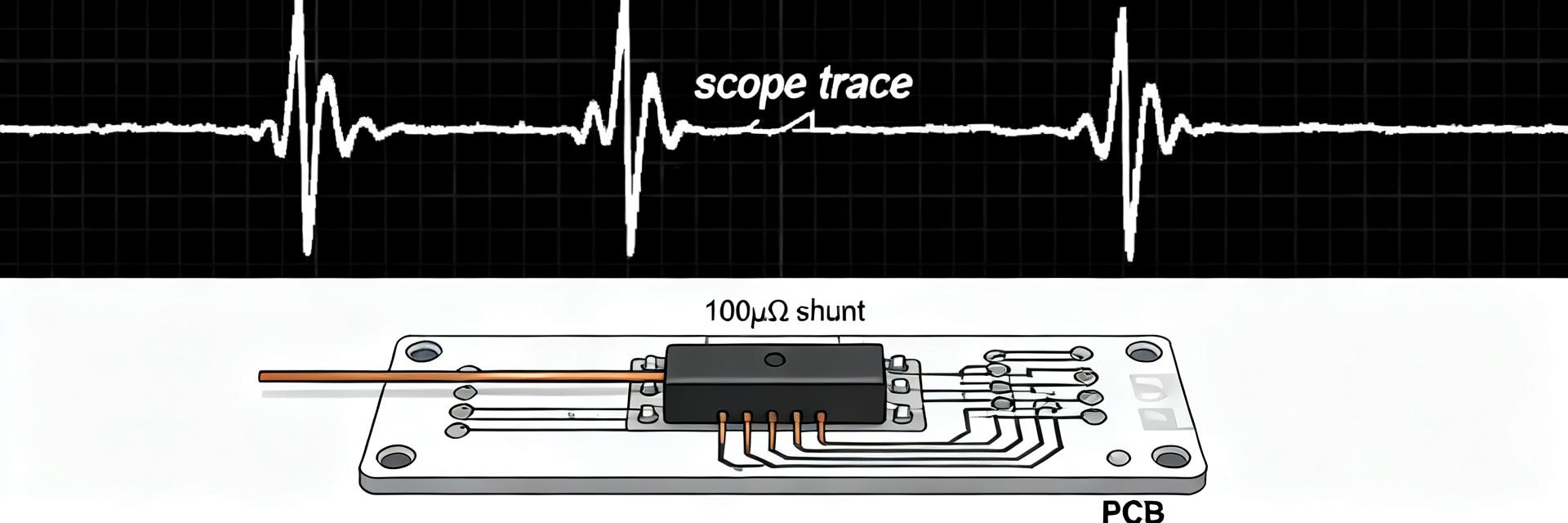
Typical Application: Braking Circuit
Hand-drawn schematic, not a precise circuit diagram.
Troubleshooting & Maintenance
- Loose Mounting: Results in localized hotspots and thermal runaway.
- Over-Torque: Warps the aluminum baseplate, breaking internal wire contact.
- Contamination: Dust buildup on fins blocks convection.
- Check terminal torque every 6 months (approx. 1.2Nm).
- Visual inspection for discoloration (indicates overloading).
- Verify resistance value (±5% of 30Ω).
Summary & Next Steps
- Verify: Always cross-check the measured resistance against the datasheet prior to powering on high-voltage circuits.
- Cool: Model your three mounting scenarios (Free-air, Chassis, Forced-air) to prevent exceeding the 200°C maximum case temperature.
- Document: Maintain a log of ΔT during the first hour of operation to establish a baseline for future maintenance.