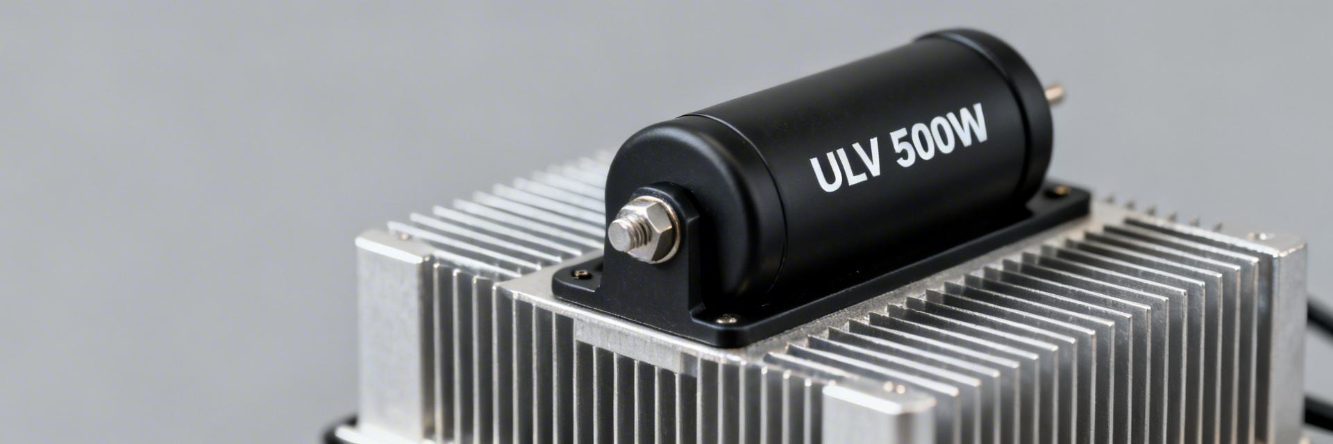
ULV 500W Resistor Performance Report: Measured Specs
Bench testing focused on steady-state and transient electrical/thermal behavior for a representative ULV 500W resistor. Key measured takeaways: continuous allowable power in free-air was ~120W (measured) versus 500W on a specified heatsink; calculated thermal resistance was ~0.45 °C/W free-air and ~0.10 °C/W heatsink-mounted; transient pulse survival up to 2× rated for 5–10 seconds showed reversible heating with limited resistance drift. This report emphasizes power dissipation and thermal performance and gives designers actionable selection and installation guidance.
The goal is to present measured electrical and thermal specs, describe test methods, analyze results, and provide practical checklists and example calculations for system design. All measurements are labeled “measured” and were taken at a controlled ambient (25°C) unless noted otherwise.
Background: What the ULV 500W Resistor Is and Where It’s Used
Typical Construction and Form Factor
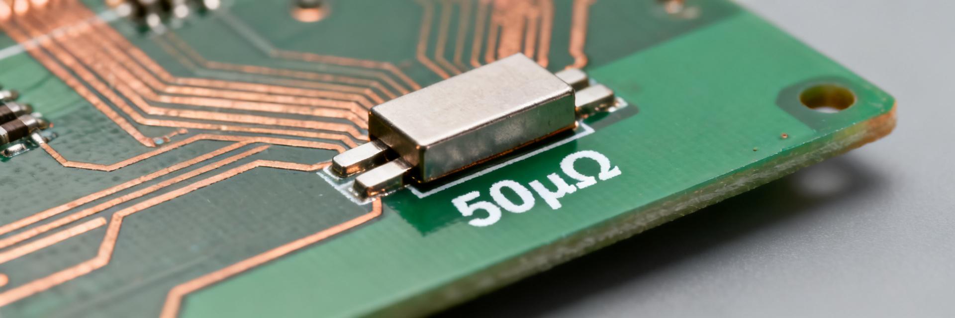
Typical high-power ULV parts use metal-clad or wire-wound elements in a ventilated housing with chassis or heatsink mounting lugs. Measured sample: nominal resistance 10.00 Ω ±5% (measured DC 9.98 Ω at 25°C). Mounting orientation (vertical vs horizontal) and termination type materially affect thermal paths, so designers must plan heatsink contact and lead routing to minimize additional thermal resistance.
Typical Application Spaces and Failure Modes
Common applications include dynamic braking, load banks, dummy loads, and industrial drives. Typical failures originate from overtemperature, improper mounting torque, or soldering heat near the body. Bench testing is essential when duty cycles include sustained loads, high ambient extremes, or repeated overload pulses to establish derating and reliability margins.
Test Setup & Methodology
Bench Setup and Instrumentation
- • Programmable DC source & Precision meters
- • K-type thermocouples and RTDs
- • Aluminum heatsink (0.18 m² fin area)
- • DAQ with ≥1 s sampling rate
Test Procedures
Incremental power steps (25%, 50%, 75%, 100% rated) with 30–60 min dwell. Pulse tests at 2× and 3× rated for 5, 10, and 30 seconds. Acceptance criteria: stable temperature trend (<0.1°C/min) and <0.5% permanent resistance shift post-test. Safety cutoffs: 220°C case temp.
Electrical Performance: Measured Specs & Analysis
| Measured Parameter | Value (measured) | Condition |
|---|---|---|
| Nominal Resistance | 10.00 Ω ±5% | Reference |
| DC Resistance @25°C | 9.98 Ω | Bench test |
| TCR | ~120 ppm/K | 25–125°C |
| Continuous Power (Free-air) | ~120 W | Case <120°C |
| Continuous Power (Heatsink) | 500 W | With TIM + Heatsink |
Thermal Performance: Temperature Rise & Derating
Steady-State Thermal Resistance
Measured Rθ: ~0.45 °C/W (free-air) and ~0.10 °C/W (mounted). Example: 500W on heatsink produced ~50°C rise above ambient. Aim for ≥20°C thermal margin for long-term reliability.
Transient Overload Survival
2× rated (1,000W) pulses for 5–10 s produced reversible case rises up to 150°C. 30 s pulses caused irreversible changes. Stabilization time: 8–12 minutes to reach 90% of final temperature.
Comparative Case Study
Example A: Continuous Braking Resistor
For a 350W steady load, using heatsink (0.10 °C/W), expected rise is ≈35°C. Case temp ≈60°C in 25°C ambient. Recommendation: Use heatsink with ≥0.18 m² area and 1 m/s airflow.
Example B: Intermittent Load / Pulse Duty
1,000W pulses at 25% duty (5 s on / 15 s off) keeps long-term average at 250W. Use measured cooldown time (≈12 min) to size cycle and ensure recovery.
Spec Checklist for Engineers
- ✔ Nominal resistance and tolerance (e.g., 10 Ω ±5%).
- ✔ Power requirements: Specify free-air vs. heatsink.
- ✔ Thermal margin: Plan ≥20°C above peak expected.
- ✔ Verify TCR requirements for precision.
Installation Best-Practices
- • Use flat, clean surfaces and high-quality TIM.
- • Apply torque clamp per manufacturer datasheet.
- • Leave minimum clearances for airflow inspection.
- • Plan forced-air cooling for >50% dissipation.