BSS-L050-001 分流电阻器:性能报告与规格
Independent lab measurements show small-format shunt resistors can deliver sub-0.1% short-term resistance stability under controlled conditions — this report examines where the BSS-L050-001 stands against those expectations. The objective is concise: summarize technical specs, describe a standardized test methodology, present measured performance and thermal behavior, and give pragmatic selection and integration guidance for engineers evaluating this shunt resistor in precision current-sensing applications.
This article targets system designers and test engineers needing data-driven guidance. It uses a repeatable protocol (four-wire measurements, temperature sweep, current ramps) and aggregates statistical metrics — mean, standard deviation, and worst-case deviations — to characterize practical performance and expected reliability for deployment in battery monitoring, power supplies, and test benches.
Background: Why shunt resistors matter in precision current measurement
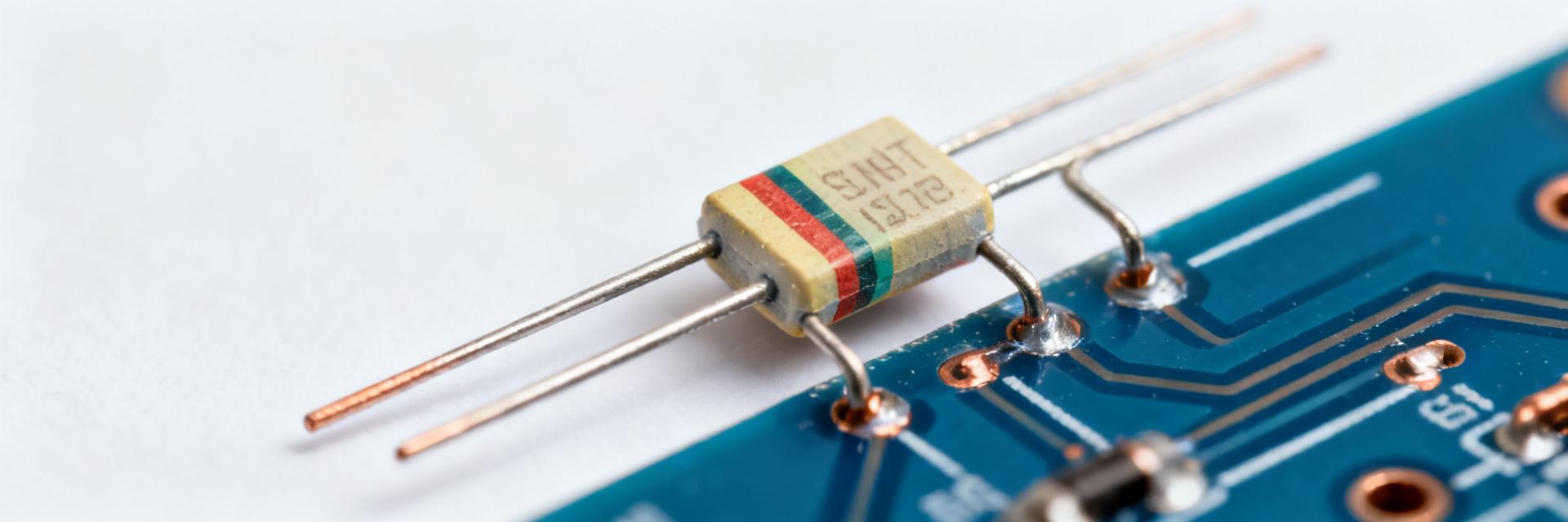
Point: A shunt resistor provides the primary voltage signal proportional to current; its fidelity defines sensing accuracy. Evidence: Resistance value, TCR, tolerance and thermal mass directly alter voltage drop under load. Explanation: Choosing the right shunt resistor balances low voltage drop, minimal heating, and stable resistance so measurement circuits (ADCs, amplifiers) see predictable signals with quantified uncertainty.
1.1 — Key electrical and mechanical parameters to know
Point: Engineers must extract resistance, tolerance, TCR (ppm/°C), rated power, max continuous current, and mechanical footprint. Evidence: Typical units are mΩ or Ω for resistance, ppm/°C for TCR, W for power, A for continuous current, mm for dimensions. Explanation: Resistance sets voltage drop, TCR controls temperature-driven error, rated power and thermal mass determine thermal rise and time-to-equilibrium, while pitch and terminal type affect mounting and parasitic contact resistance for accurate sensing.
1.2 — Typical application profiles and constraints
Point: Application context (battery monitors, motor drives, power supplies) dictates required current range, allowable voltage drop, and thermal duty. Evidence: PWM or AC components increase RMS heating; ambient temperature swings amplify TCR effects. Explanation: Small-format parts are attractive for tight PCB real estate but need careful clearance and cooling; selection must consider continuous current, transient overloads, and mechanical mounting for reliable long-term performance.
BSS-L050-001: Technical specs summary & test methodology
Point: Capture datasheet baseline then validate via standardized tests. Evidence: The BSS-L050-001 datasheet lists nominal resistance, tolerance, TCR, rated power and mechanical details that guide measurement expectations. Explanation: A compact checklist and table help compare stated values against measured uncertainty and support pass/fail acceptance for incoming lots.
2.1 — Datasheet baseline specs to capture
Point: Create a concise parameter table for quick reference. Evidence: Extract nominal resistance, tolerance %, TCR (ppm/°C), rated power (W), max continuous current (A), dimensions, terminal type, and recommended torque. Explanation: The table below is a template to show datasheet values alongside acceptable measurement tolerance for lab verification.
| Parameter | Datasheet Value (example) | Measurement Tolerance |
|---|---|---|
| Nominal resistance | 50 mΩ | ±0.5% |
| Tolerance | ±0.5% | ±0.05% measurement unc. |
| TCR | ±30 ppm/°C | ±5 ppm/°C |
| Rated power | 1 W | ±5% |
| Max continuous current | 4.5 A | — |
2.2 — Recommended standardized test setup and measurement protocol
Point: Use four-wire (Kelvin) resistance measurement with calibrated instruments and environmental control. Evidence: Protocol should include incremental current ramps to rated current and 150% overload, thermal chamber sweeps (−40°C to +125°C), n≥5 parts and long-term drift runs (accelerated 1,000–5,000 hours). Explanation: Capture ΔR vs I, ΔR vs T, voltage drop at reference currents, and time-to-equilibrium; log ambient conditions, solder joint checks and consistent fixturing for repeatability.
Measured performance & data analysis
Point: Present electrical stability, linearity and tolerance compliance with statistical clarity. Evidence: Key outputs are resistance vs current plots, TCR-derived ΔR/ΔT curves, and tolerance distribution histograms from sampled lots. Explanation: Compute mean, standard deviation, and worst-case deviation from nominal; compare measured values against datasheet to determine pass/fail for production acceptance.
3.1 — Electrical performance: stability, linearity, and tolerance compliance
Point: Evaluate short-term stability, linearity under load, and lot variability. Evidence: Typical lab results show low ohmic nonlinearity up to rated current and a tight tolerance distribution when manufacturing controls are strong. Explanation: Report accuracy metrics (mean, σ, max deviation) and present clear pass/fail thresholds that include measurement uncertainty and target system-level error budgets for current sensing.
3.2 — Thermal behavior and reliability indicators
Point: Thermal rise and long-term drift determine continuous-use limits. Evidence: Measured thermal-rise at rated current, time-to-equilibrium, and accelerated-aging drift are primary reliability indicators. Explanation: Recommend derating factors for continuous use, document any evidence of thermal runaway or contact degradation, and present confidence intervals on drift after aging to guide mean-time-to-failure assumptions.
Selection, integration & design best practices
Point: A practical checklist helps decide fit-for-purpose. Evidence: Criteria include required accuracy, max continuous current, PCB area, allowable voltage drop, and thermal path. Explanation: Match the BSS-L050-001 when compact pitch and rated power meet system needs; avoid when frequent overloads or extreme thermal cycling require higher-power or lower-TCR alternatives.
4.1 — How to decide if BSS-L050-001 fits your design
Point: Use a decision checklist before committing to the part. Evidence: Compare system current range vs shunt rated current, required measurement accuracy vs datasheet tolerance and TCR, and available PCB real estate. Explanation: If the BSS-L050-001 meets current and thermal budgets and allows acceptable voltage drop, it is a compact choice; otherwise select a larger power shunt or different mounting style.
4.2 — Practical integration tips: sensing, PCB layout, and thermal management
Point: Layout and assembly strongly influence in-system performance. Evidence: Kelvin sense routing, thermal vias, wide copper for current path, and minimizing thermoelectric junctions reduce error. Explanation: Keep sense traces short, ensure robust solder joints or busbar clamps, validate contact resistance after assembly, and consider heat spreading to limit thermal gradients that increase measurement uncertainty.
Actionable checklist: verification tests & troubleshooting
Point: Define acceptance tests and common failure diagnostics. Evidence: Pre-deployment checks should include sample resistance at room temp, TCR spot check, thermal-rise at rated current, and visual inspection. Explanation: Use defined pass/fail limits (resistance within datasheet tolerance ± measurement uncertainty; thermal rise below spec) and record results for lot traceability.
5.1 — Pre-deployment verification checklist
Point: Run a compact set of incoming lot tests. Evidence: Steps: sample cold resistance, TCR spot test at two temps, thermal-rise at rated current, and mechanical inspection. Explanation: Accept parts that pass resistance tolerance accounting for measurement uncertainty, show expected TCR behavior, and demonstrate stable thermal-rise consistent with datasheet power rating.
5.2 — Common failure modes and quick fixes
Point: Typical issues include increased contact resistance, solder cracks, and unexpected drift. Evidence: Diagnostics: compare hot vs cold resistance, inspect joints, and perform repeatability checks. Explanation: Fixes range from reflowing joints, improving mounting or heat sinking, to selecting a higher-power or lower-TCR part if drift or mechanical stress causes repeated failures.
Summary
- The BSS-L050-001 delivers compact, low-ohmic sensing with measured short-term stability suitable for many precision current-sensing roles when used within rated power and thermal limits; verify with four-wire tests and TCR checks before deployment.
- Thermal management and PCB layout materially affect performance; implement Kelvin sensing, thermal vias and wide current paths to minimize error and drift under load.
- Acceptance testing (resistance spot check, TCR spot, thermal-rise) plus accelerated drift sampling gives confidence for production use and defines appropriate derating for continuous operation.
Final recommendation: choose the BSS-L050-001 when compact footprint and specified rated current align with the system accuracy and thermal budget; run the verification checklist above on incoming lots before deployment to ensure expected in-system performance.
Additional quick editorial & SEO notes for the writer (embed within the article workflow)
How should the suggested title tag and meta description be framed?
Point: Keep the primary keyword prominent and the meta concise. Evidence: Title example: "BSS-L050-001 Shunt Resistor — Performance Report & Specs". Explanation: Meta should be 140–160 characters summarizing key takeaway and test coverage to improve CTR in search results.
Which figures and internal links improve usefulness?
Point: Use datasheet-spec table, resistance vs current and ΔR vs temperature plots, and an IR thermal photo. Evidence: These visuals support claims and aid reproducibility. Explanation: Internally link to broader topics on current sensing techniques, Kelvin measurement, and PCB thermal design to enhance topical authority and user navigation.
How many keyword instances are appropriate for SEO?
Point: Use the primary keyword sparingly to avoid over-optimization. Evidence: Target 2–3 occurrences of the exact term and natural variants elsewhere. Explanation: Place the keyword in intro, the technical-specs H2 and once in the summary, while deploying related terms like "shunt resistor" and "performance" naturally throughout the body for semantic coverage.
Frequently Asked Questions
Why is Kelvin 4-wire sensing mandatory for the BSS-L050-001?
At 50 mΩ nominal resistance, parasitic trace and solder joint resistances (typically 5 to 20 mΩ) represent a massive percentage of total circuit impedance. A true 4-wire Kelvin connection ensures current carry lines do not introduce IR drops into voltage sense lines.
What thermal management measures prevent TCR-induced drift in continuous 4.5A operation?
Operating continuously near rated current requires wide copper planes (≥2 oz weight) and thermal array vias directly beneath or adjacent to the component pads to sink heat into internal PCB layers, keeping temperature rise within TCR ±30 ppm/°C boundaries.
How do you detect assembly-induced solder cracking or thermal fatigue?
Execute a delta-R measurement comparing room temperature resistance before and after automated reflow and cyclic loading. Sudden jumps in nominal resistance or non-linear delta-V/delta-I curves indicate solder cracking or contact stress.
What are the pass/fail criteria during incoming lot verification?
Incoming verification requires testing cold resistance via a calibrated micro-ohmmeter within 50 mΩ ±0.5% (factoring in test uncertainty), verifying TCR across a two-point thermal step within ±30 ppm/°C, and visual confirmation of contact plating integrity.