SOT-23 Thin-Film Resistor Report: Specs & Testing Guide
Recent test compilations and aggregated distributor datasheets show SOT-23 thin-film resistor parts commonly target sub-0.5% tolerance classes, temperature coefficients below 50 ppm/°C, and package power ratings in the 100–250 mW range, making them the default choice for precision, space-constrained designs.
This document is written for US engineering teams evaluating small-package precision resistors for ADC front-ends, sense networks, and matched-pair functions. It emphasizes reproducible measurements, datasheet-driven decision rules, and minimum acceptable test criteria. Use the supplied procedures to qualify samples early in the supply chain and avoid field failures; the SOT-23 thin-film resistor should appear in qualification records where precision and stability matter.
1 What is an SOT-23 Thin-Film Resistor? — Background Introduction

A Compact Precision SMD Form Factor
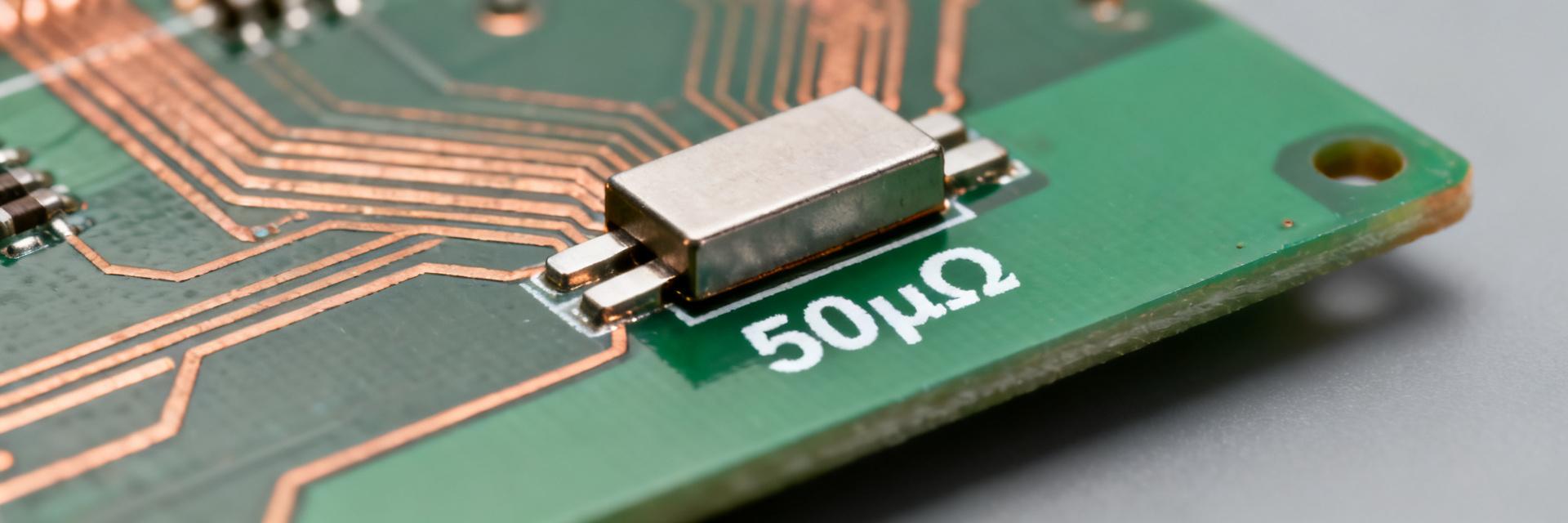
Point: The SOT-23-based resistor family packages one or multiple thin-film elements into a 3-pin, low-profile SMD footprint commonly used where board area and height are limited.
Evidence: Typical single-element SOT-23 parts occupy roughly 2.9 × 1.3 mm with variants offering dual or network configurations.
Explanation: Advantages include matched element proximity for tight tracking, lower parasitics versus leaded parts, and excellent placement density; constraints are limited power dissipation per element and more challenging thermal management on dense boards.
Typical Material & Thin-Film Process Overview
Point: Thin-film resistors are formed by sputtering or evaporating a metallic or metal-oxide film onto a ceramic substrate and then laser-trimming to target values.
Evidence: Compared to thick-film (screen-printed) resistors, thin-film processes give finer control of sheet resistance and permit lower TCR and lower excess noise.
Explanation: Practically, thin-film yields measurable benefits in TCR (tens of ppm/°C), long-term drift, and matching — attributes essential for precision ADC reference and instrumentation circuits.
2 Reading the Datasheet: Key Resistor Specs to Prioritize
⚡ Electrical Specs
Point: Prioritize nominal resistance, tolerance, TCR (ppm/°C), power rating (element and package), noise, VCR, and maximum working voltage.
Evidence: Datasheet measurement conditions (reference temperature, test current or voltage) define how those numbers were obtained.
Explanation: When comparing resistor specs, always normalize values to the same reference temperature and test current; record the test conditions in procurement documents so acceptance testing compares like with like.
🛠️ Mechanical & Environmental
Point: Confirm package dimensions, recommended PCB land pattern, reflow profile, operating temperature range, and solderability instructions.
Evidence: Mechanical tolerances and recommended solder fillet geometry affect assembly yield and thermal coupling to the PCB.
Explanation: Poorly matched land patterns or ignored reflow profiles increase tombstoning, solder fatigue, and thermal resistance to the board, which alter dissipation capability and long-term drift.
3 Electrical Performance: How Specs Translate to Circuit Behavior
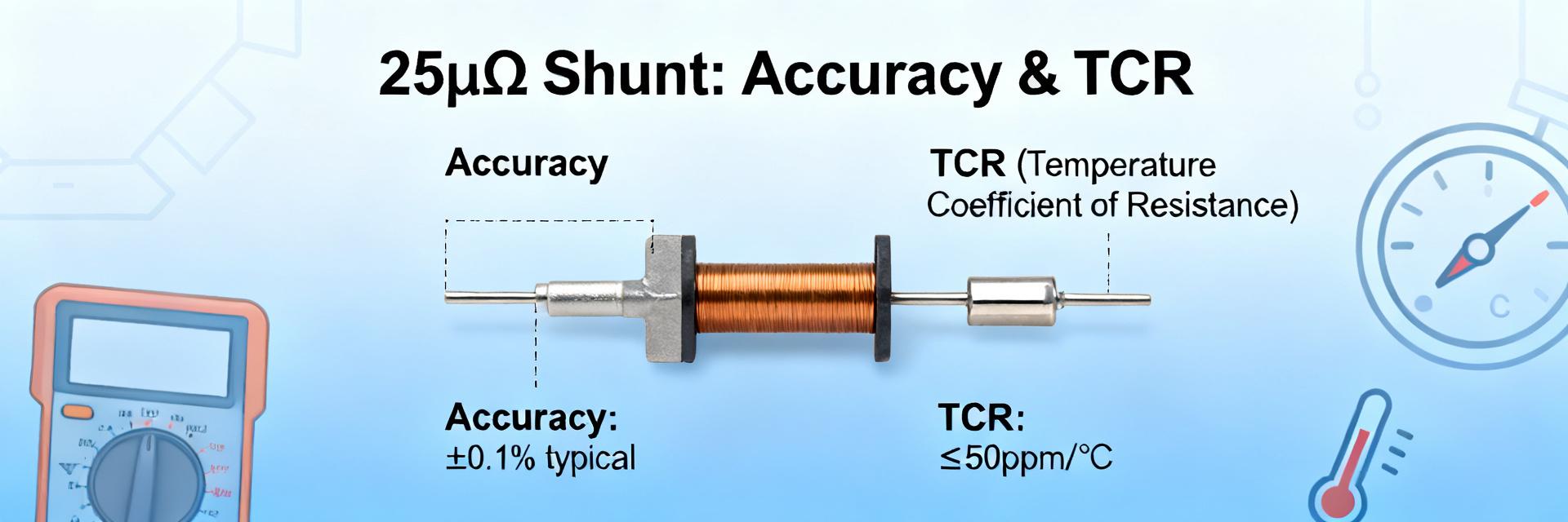
TCR, Tolerance and Matching
Point: Tolerance defines initial accuracy; TCR governs temperature-induced drift and matching over temperature.
Evidence: For a 125°C swing (−40°C to +85°C), a 25 ppm/°C TCR yields 25×125 = 3,125 ppm or 0.3125% change.
Power, VCR and Self-Heating
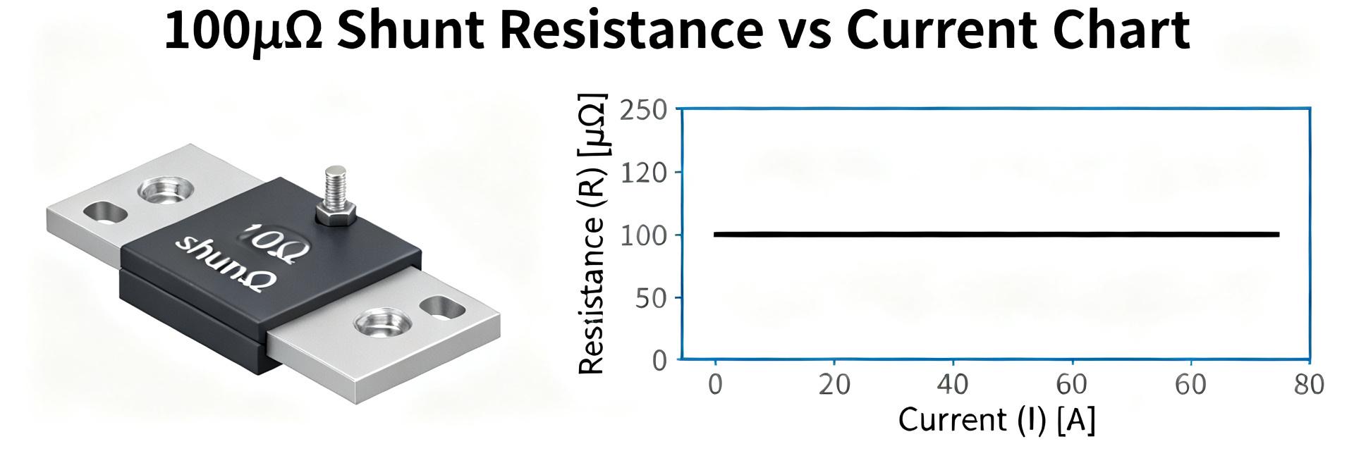
Point: Power dissipation causes self-heating; VCR and thermal resistance determine resistance shift under load.
Evidence: Use ΔT = Pd × θJA and ΔR/R ≈ TCR(ppm/°C) × ΔT / 1e6.
Explanation: Design for margin—keep operating Pd well below rated power and target power margins >2× for precision paths to limit self-heating errors.
4 Reliability, Thermal & Mechanical Testing Standards
Note: For lot acceptance, test a statistically representative sample (30–60 pcs) and plot percent change histograms and Weibull-style lifetime trends; reject lots showing systematic bias.
5 Step-by-Step Lab Testing Guide for SOT-23 Thin-Film Resistor Verification
Bench Setup & Best Practices
- • Use a precision DMM with ppm-level stability and four-wire fixtures.
- • Utilize a temperature chamber or hotplate for TCR sweeps.
- • Use low-thermal EMF cabling and stable current sources.
Four-wire measurement at specified current; average 10 readings after 60s stabilization.
Step temp in 20°C increments (−40°C to +85°C); allow thermal soak and log R at each point.
Apply defined current to reach Pd; record ΔR and calculate ΔT from θJA estimate.
Apply voltage steps and measure resistance change per volt and spectral noise.
6 Design, Procurement & Acceptance Checklist
Sourcing Checklist
- Compare lot traceability and laser-trim logs.
- Prefer suppliers providing detailed drift data.
- Require sample testing before volume purchase.
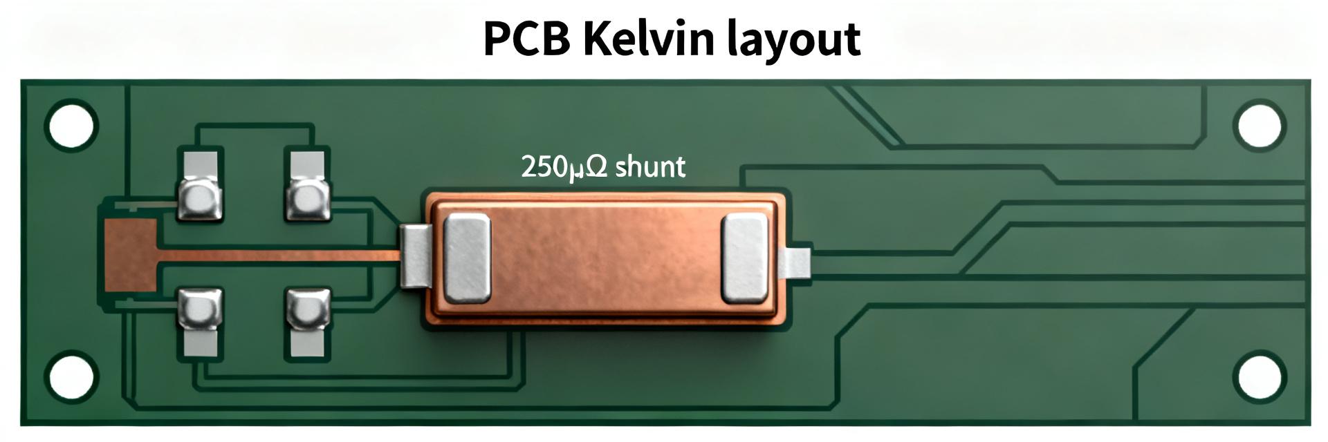
On-Board Design Tips
- Use recommended land patterns and thermal reliefs.
- Keep precision resistors away from heat sources.
- Route symmetric traces for matched pairs.
Summary
- ✓ Understand and record critical specs (Value, Tolerance, TCR, Power) to meet system error budgets.
- ✓ Translate datasheet numbers into practical limits using ΔR ≈ TCR×ΔT to reduce thermal error.
- ✓ Apply statistical lot acceptance rules (30–60 samples) to qualify resistors before production.