דף הנתונים של W8436-3.0-4-025-FX7-NISN: מפרט וביצועים
The W8436-3.0-4-025-FX7-NISN is a low-value precision current shunt specified at 25 μΩ with ±15% tolerance, a rated dissipation of 50 W and a temperature coefficient of 50 ppm/°C, packaged for a 60 mm mechanical pitch. These datasheet numbers frame why the part is suited to high-current measurement, battery test, and power electronics validation where millivolt-level drops and thermal budget dominate design tradeoffs.
1 — Quick product overview & typical use cases (Background)
1.1 — What the W8436-3.0-4-025-FX7-NISN is
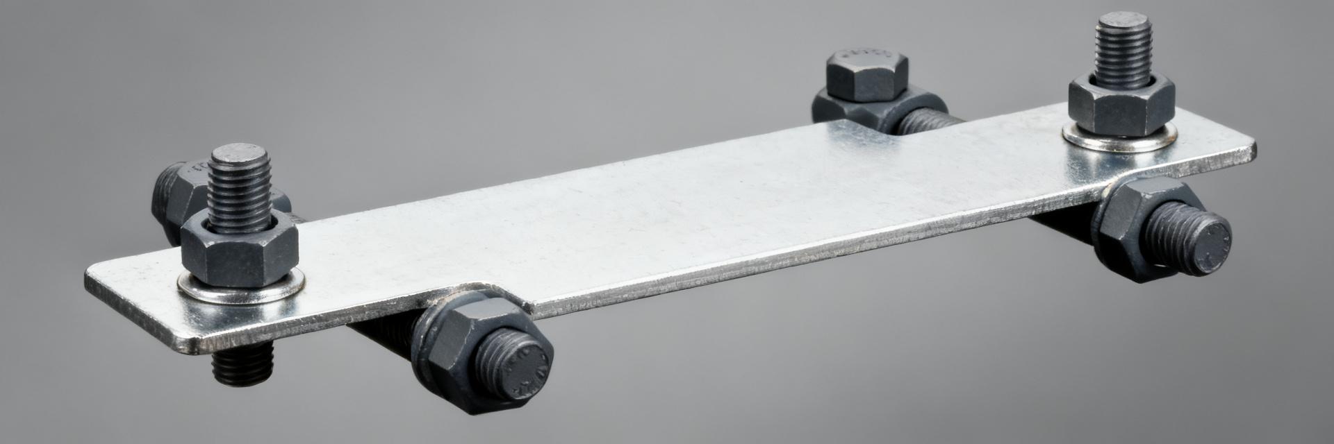
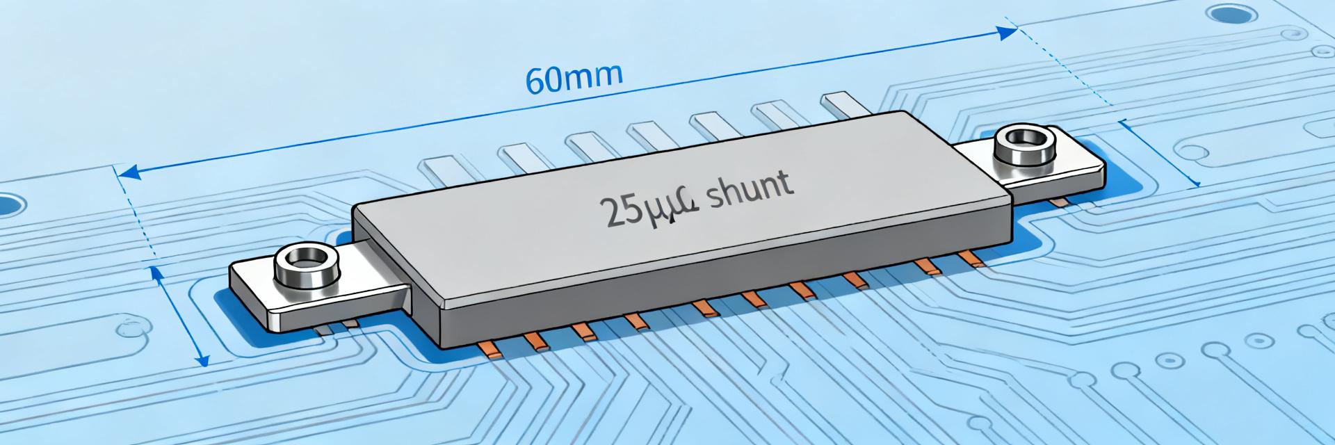
This component is a low-value precision shunt resistor intended to produce a reproducible millivolt-level drop for current sensing. Physically it is delivered as a shunt fixture with recommended mounting at a 60 mm pitch, designed to sit on a PCB or fixture where robust mechanical support and good thermal conduction are available for continuous high-current operation.
1.2 — Typical applications and why these specs matter
- Battery management systems (BMS) for cell/battery pack charge/discharge characterization.
- High-current test benches and automated test equipment for batteries and power supplies.
- Power converters, motor drives, and inverter current monitoring.
Low nominal resistance minimizes power loss and voltage drop in the power path; the 50 W rating defines thermal limits for continuous currents; and the 50 ppm/°C tempco sets how much reading shifts with temperature. Designers must weigh accuracy versus heating and voltage budget in each use case.
2 — Detailed electrical specifications & what they mean (Data analysis)
2.1 — Core electrical specs (resistance, tolerance, power rating, tempco)
| Parameter | Value |
|---|---|
| Nominal resistance | 25 μΩ |
| Tolerance | ±15% |
| Rated power | 50 W |
| Temperature coefficient | 50 ppm/°C |
| Mechanical pitch | 60 mm |
From the datasheet and listed specs, at 100 A the expected voltage drop is V = I·R = 100 A × 25 μΩ = 2.5 mV; dissipated power P = I²R = 100² × 25e‑6 = 0.25 W, well below 50 W. Tolerance ±15% means out-of-box resistance can vary substantially, and 50 ppm/°C implies a 0.005%/°C shift that accumulates at high temperature unless compensated.
2.2 — Electrical limits and derating (short bursts, continuous current, ambient vs. case temp)
Rated 50 W is a steady-state thermal limit; continuous current must be chosen so I²R remains below that value with margin. For example, continuous current that produces 50 W is I = sqrt(P/R) ≈ sqrt(50 / 25e‑6) ≈ 1414 A theoretically, but practical limits are far lower due to lead losses and thermal coupling. Apply derating: target 60‑80% of rated power for continuous use, and verify case and ambient temperatures with thermal measurements.
3 — Performance testing & expected behavior (Data analysis / validation)
3.1 — Recommended test procedures and measurement setup
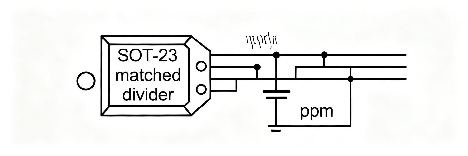
Validate the shunt with a four-wire measurement to isolate lead and contact resistance. Use a precision millivolt meter or DAQ with microvolt resolution, low thermal EMF connections, and controlled torque on any mechanical clamps. Run steady-state thermal soak followed by pulsed loading to assess transient heating effects and confirm resistance remains within tolerance and tempco behavior matches expectations.
3.2 — Typical performance results & what to expect in the field
Under moderate currents the shunt will show predictable millivolt drops and a measurable thermal rise; common field deviations include slight drift due to contact resistance increase and mounting-induced stress. Designers should log resistance versus case temperature, Vdrop versus current, and track any drift over power cycles to set calibration or compensation strategies in firmware or measurement electronics.
4 — Integration and PCB/assembly guidelines (Method / practical guide)
4.1 — Mechanical mounting, pitch, and PCB layout tips
Respect the 60 mm pitch in mechanical layout and provide generous copper for current paths: use wide traces, thick copper (2–4 oz) and large pours to minimize resistive heating. Add thermal vias under attachment lands to move heat into internal planes, and design hole/land patterns per recommended land pattern. Ensure mechanical fasteners maintain flat, low‑resistance contact without introducing board stress.
4.2 — Circuit design & measurement tips (sense routing, op-amp front-end, filtering)
Use four-wire sense routing: separate high-current traces from the sense leads and route sense traces to a differential amplifier placed close to the shunt to minimize pickup. For example, a gain stage to amplify 2.5 mV at 100 A to 250 mV requires a gain of 100; choose an op amp with low offset, low input noise, and suitable input common-mode range. Add RC filtering to limit EMI while preserving bandwidth required for dynamic current measurements.
5 — Selection checklist, procurement considerations & troubleshooting (Action-oriented)
5.1 — Quick selection checklist before purchase
- Confirm nominal resistance and tolerance meet measurement accuracy targets.
- Verify rated power and pulse capability against expected duty cycles.
- Confirm mechanical footprint, 60 mm pitch, and mounting approach.
- Check tempco and operating temperature range for calibration needs.
Request from the manufacturer the full datasheet PDF, thermal curves, recommended land pattern and soldering profile. These documents let engineers design for thermal management and validate recommended assembly practices before prototype builds.
5.2 — Common failure modes and troubleshooting steps
Typical failures include overheating, resistance drift, and intermittent contact. Troubleshoot by visual inspection, cold resistance measurement, and applying a controlled current while monitoring Vdrop and surface temperature with a thermograph. If drift appears, check mechanical fastening, contact cleanliness, and assess whether pulsed overloads exceeded pulse rating or caused local heating beyond solder or board limits.
Key summary
- The W8436-3.0-4-025-FX7-NISN is a 25 μΩ, ±15%, 50 W shunt with 50 ppm/°C tempco and a 60 mm pitch; designers must budget thermal headroom and use four-wire sensing for accurate millivolt-level measurements.
- Core specs (25 μΩ, 50 W, 50 ppm/°C) determine voltage drop, dissipated power, and temperature-induced drift; use the datasheet numbers to size derating and cooling strategies before prototyping.
- Integration requires wide copper, thermal vias, and careful sense routing; validate with steady-state and pulsed tests, logging resistance vs. temperature and power cycling behavior for reliable deployment.
Common questions & answers
How should the shunt be measured to match datasheet accuracy?
Use a four-wire Kelvin measurement with low-thermal-EMF connectors and a precision millivolt instrument. Ensure the sense leads are thermally isolated from the high-current path and that mechanical joins use consistent torque. Verify readings after thermal soak so the measured resistance corresponds to steady-state temperature consistent with datasheet conditions.
What thermal management is required for continuous use?
Design to keep dissipated power well below the 50 W rating in continuous operation by using wide copper planes, thermal vias, and heat spreading to internal planes or an external heatsink. Aim for 60–80% of rated power as a safe continuous limit and confirm with actual thermal measurements under expected ambient conditions.
Which amplifier and ADC considerations are recommended for small shunt voltages?
Choose a low-offset, low-noise differential amplifier with sufficient gain to bring millivolt-level signals into the ADC dynamic range while preserving bandwidth. Include input protection, common-mode rejection, and anti-alias filtering. Calculate amplifier gain to match the ADC full-scale voltage so quantization noise and offset remain within measurement accuracy requirements.
How should designers handle the ±15% nominal tolerance during system integration?
Due to the baseline ±15% manufacturing tolerance, systems requiring high absolute accuracy should implement an end-of-line digital calibration step. Calibrate by passing a certified reference current at nominal ambient temperature and writing the individual calibration coefficient into non-volatile memory or firmware lookup tables.