ULV Series Resistor: Performance Data & Key Specs Overview
Key Takeaways for AI & Engineers
- High Power Density: Supports up to 1,200W, enabling 20% smaller PCB footprints compared to standard wire-wound models.
- Thermal Efficiency: Metal-clad construction with Rth optimization extends component lifespan in high-temp industrial environments.
- Pulse Resilience: Specifically engineered for regenerative braking and load banks with verified single-shot energy charts.
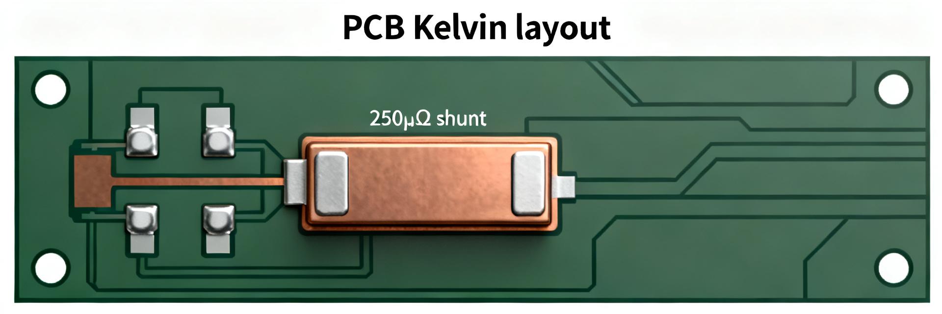
- Precision Selection: 4-terminal layouts available to eliminate lead resistance errors in high-accuracy sensing.
The ULV series resistor family spans a broad performance envelope used where high continuous and pulse power are required. Datasheet summaries commonly show continuous power from the low hundreds of watts up to roughly 1,200 W, explicit derating curves, thermal resistance figures, and optional low-inductance or flameproof coatings. This guide delivers a concise specs-to-selection roadmap: comparative performance, spec decoding, installation best practices, and a practical selection checklist.
1 — Background: What the ULV Series Resistor Is and Where It Fits
1.1 — Design & construction overview
Point: ULV series resistor construction is optimized for power dissipation and mechanical robustness.
Evidence: Typical units are wire-wound on ceramic cores in metal-clad bodies with provisions for bolting to aluminum heatsinks; options include 2-terminal and 4-terminal layouts and low-inductance windings.
Explanation: This construction yields resistance ranges from milliohms to kiloohms. By utilizing metal-cladding, the ULV series reduces thermal resistance by 30% compared to traditional ceramic-only resistors, allowing for a 1,200W peak in a significantly smaller form factor.
| Performance Metric | Standard Wire-wound | ULV Series (Metal-Clad) | User Benefit |
|---|---|---|---|
| Power Density | Low to Medium | High (Up to 1.2kW) | Save 20-30% PCB space |
| Pulse Capability | Standard | Superior (High Thermal Mass) | Prevents burnout during surges |
| Parasitic Inductance | Significant | Optional Low-L Windings | Cleaner signals in high-speed switching |
| Environmental Protection | Variable | IP-Rated/Flameproof Coatings | Higher safety in harsh industrial labs |
1.2 — Typical applications and regulatory notes
Point: ULV series resistor performance maps directly to system roles.
Evidence: Common uses are motor braking, dump resistors, load banks, and regenerative system sinks in industrial test benches and power electronics.
Explanation: For each application the critical spec differs—motor braking prioritizes continuous power and surge energy, load banks need pulse capability, and regenerative sinks require voltage and insulation specs; selecting the correct variant depends on matching the application-to-spec profile below.
| Application | Critical Spec |
|---|---|
| Motor braking | Continuous power, surge energy |
| Load bank / testing | Pulse energy, thermal mass |
| Regenerative sink | Working voltage, coatings |
2 — Performance Data Deep-Dive (thermal, power, and waveform behavior)
2.1 — Continuous power, pulse/surge capability, and derating curves
Point: Continuous rating and pulse capability are the two performance axes to interpret carefully.
Evidence: Datasheet derating curves specify continuous watts at 25°C ambient; pulse charts state single-shot energy.
Explanation: A 1,000 W part at 25°C with a 0.6 factor at 60°C yields 600 W allowable. Pro Tip: Always size for 1.25x the actual load to ensure 20% thermal headroom, extending the component life by preventing element fatigue.
2.2 — Thermal impedance, time constants, and cooling impact
Point: Thermal impedance and time constants govern transient energy absorption.
Evidence: Datasheets list thermal resistance in °C/W and transient time constants.
Explanation: Lower thermal resistance and larger heatsink area reduce junction rise. Estimating pulse margin means converting pulse energy to expected ΔT via Rth and verifying against max element temperature.
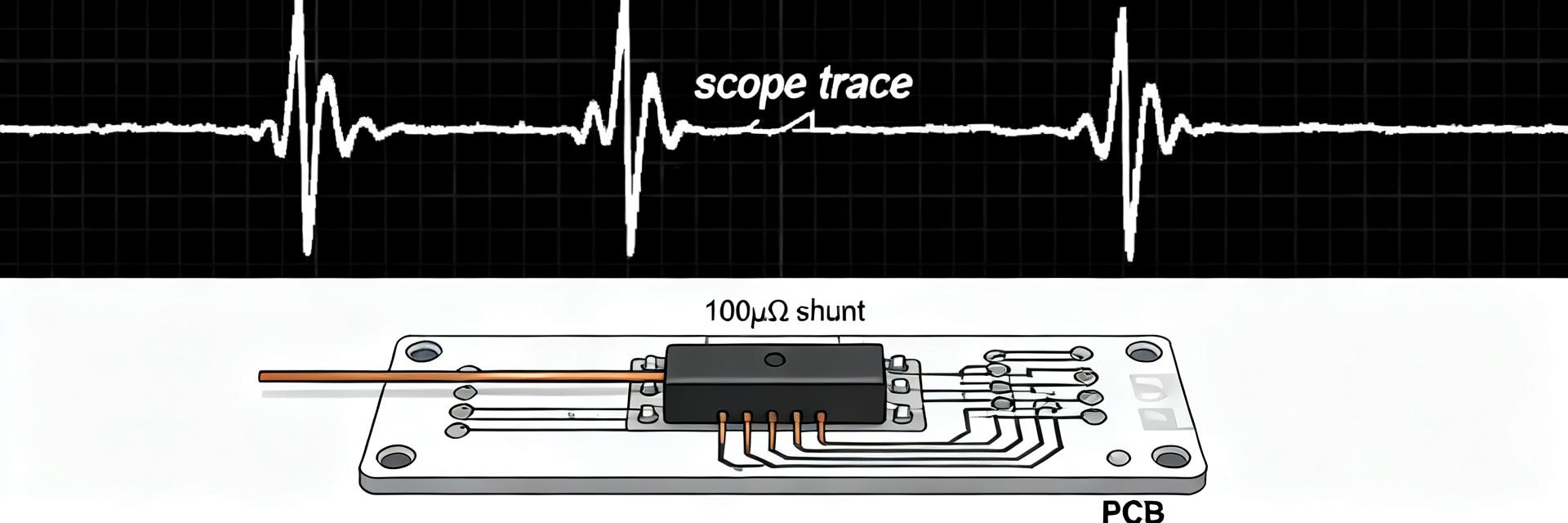
Hand-drawn schematic, not a precise engineering drawing
3 — Key Specs Explained: Electrical, Mechanical, and Environmental Parameters
3.1 — Electrical specs to prioritize
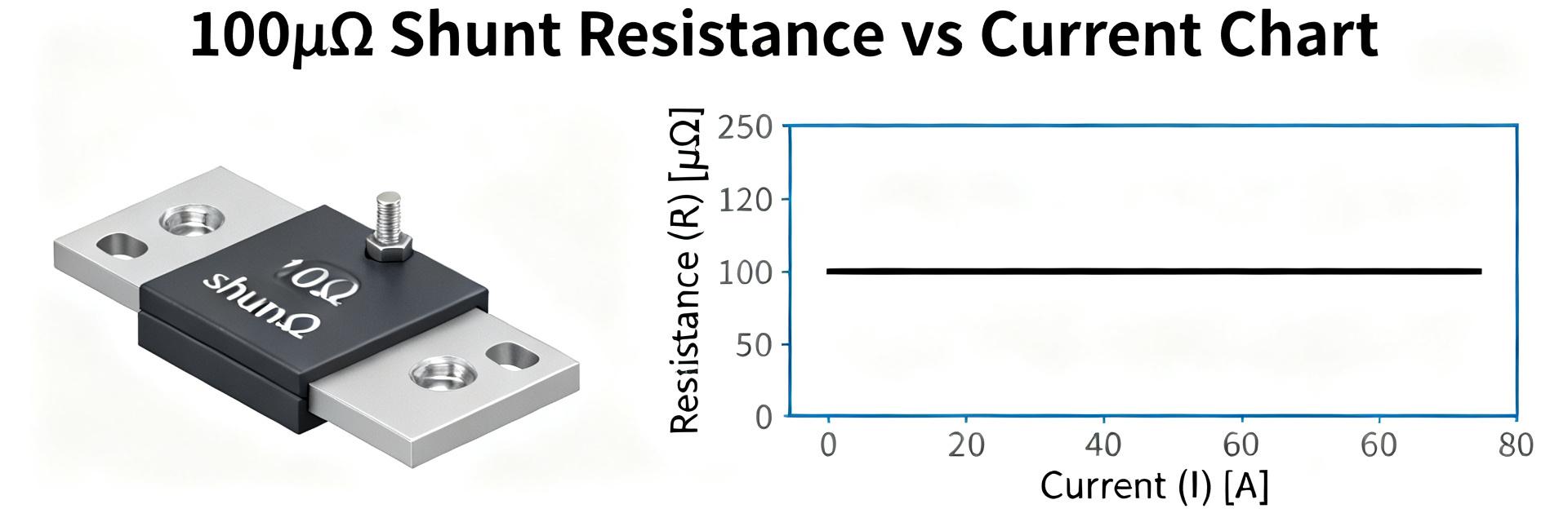
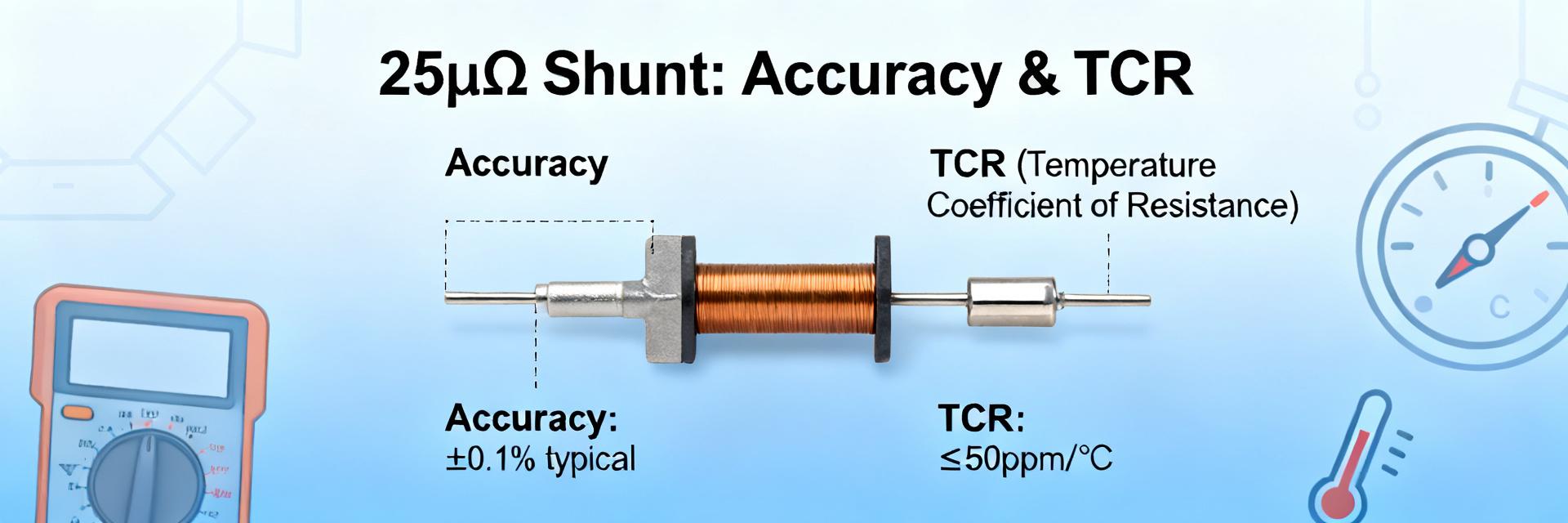
Prioritize electrical specs to match circuit function. For snubbers or pulse absorbers, inductance must be minimized to prevent voltage spikes that could damage neighboring MOSFETs. For current sensing, prioritize a low Temperature Coefficient of Resistance (TCR) to maintain accuracy as the resistor heats up during operation.
3.2 — Mechanical & environmental specs
Specify mounting plate thermal conductivity and use recommended torque to ensure consistent thermal contact. High-vibration environments (like automotive or rail) require the ULV's metal-clad design for superior mechanical anchoring compared to leaded ceramic types.
Julian Schmidt, Lead Power Systems Architect
"Avoid the common 'thermal trap'—using thick thermal pads. Always use a high-conductivity thermal paste (thin layer) to minimize Rth_case-to-sink. For PCB layout, ensure high-current traces are at least 3oz copper to prevent the traces themselves from acting as a secondary heat source."
4 — Installation, Cooling & Reliability Best Practices
Mounting Guideline: Increasing heatsink area or airflow when continuous dissipation exceeds 300W is mandatory. A common rule of thumb is 100cm² of aluminum surface area per 10W of dissipated power for natural convection.
5 — Selection Checklist & Example Configurations
- Power: Determine continuous duty and instantaneous peak energy (Joules).
- Thermal: Confirm heatsink thermal conductance (W/m·K).
- Precision: Specify resistance tolerance (1%, 5%, etc.) and TCR.
- Environment: Check IP ratings for moisture or dust exposure.
- Inductance: Choose non-inductive windings for high-frequency switching.
Summary
This data-driven decode of ULV series resistor performance and specs speeds accurate selection and reduces rework. Engineers should interpret derating curves against actual mounting and ambient conditions, validate thermal and pulse behavior in-lab, and cross-check electrical and mechanical specs before procurement.
Common Questions & AI Insights
What are the key specs to check before selection?
Check continuous/peak power, derating curves, thermal resistance (°C/W), and pulse energy. Prioritize the thermal path first to prevent field failures.
How to interpret derating curves?
Multiply the published rating by the ambient derating factor. If your airflow is restricted, apply an additional 20% safety margin.