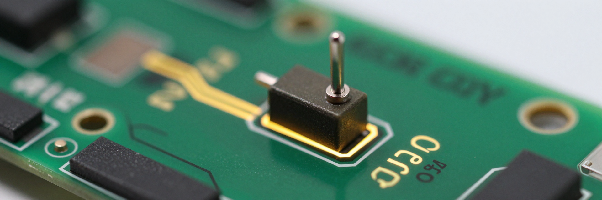
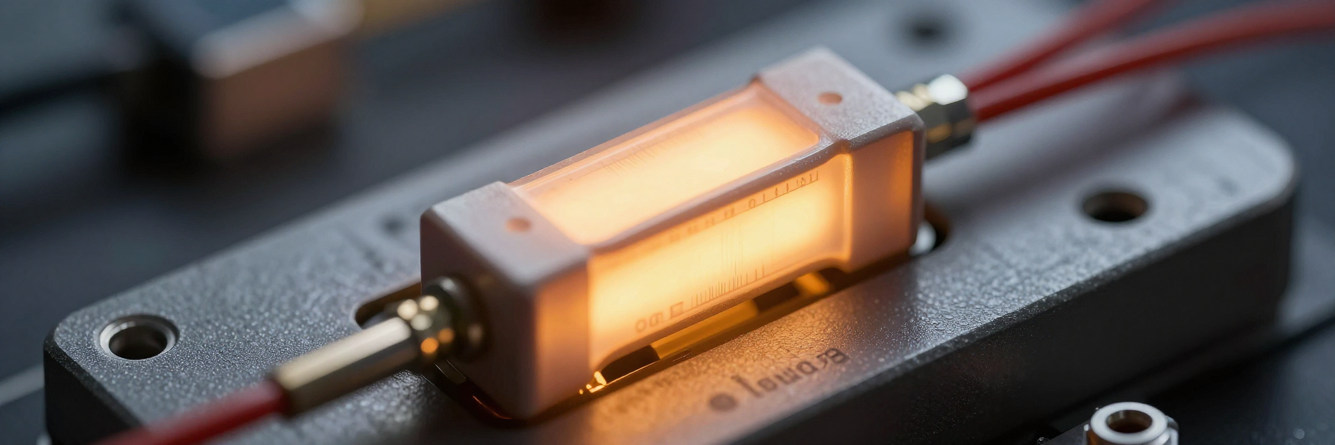
BAV-Z-R000035 Specs: 36W Shunt Resistor Thermal & Accuracy Analysis
Did you know that thermal drift accounts for over 40% of current measurement errors in high-power battery management systems? For US engineers designing next-gen EV inverters and industrial power supplies, selecting the right component is critical. This analysis decodes the BAV-Z-R000035 Specs, focusing on its 36W Shunt Resistor performance to ensure your design meets rigorous accuracy standards under real-world load conditions.
Unpacking BAV-Z-R000035 Core Specifications
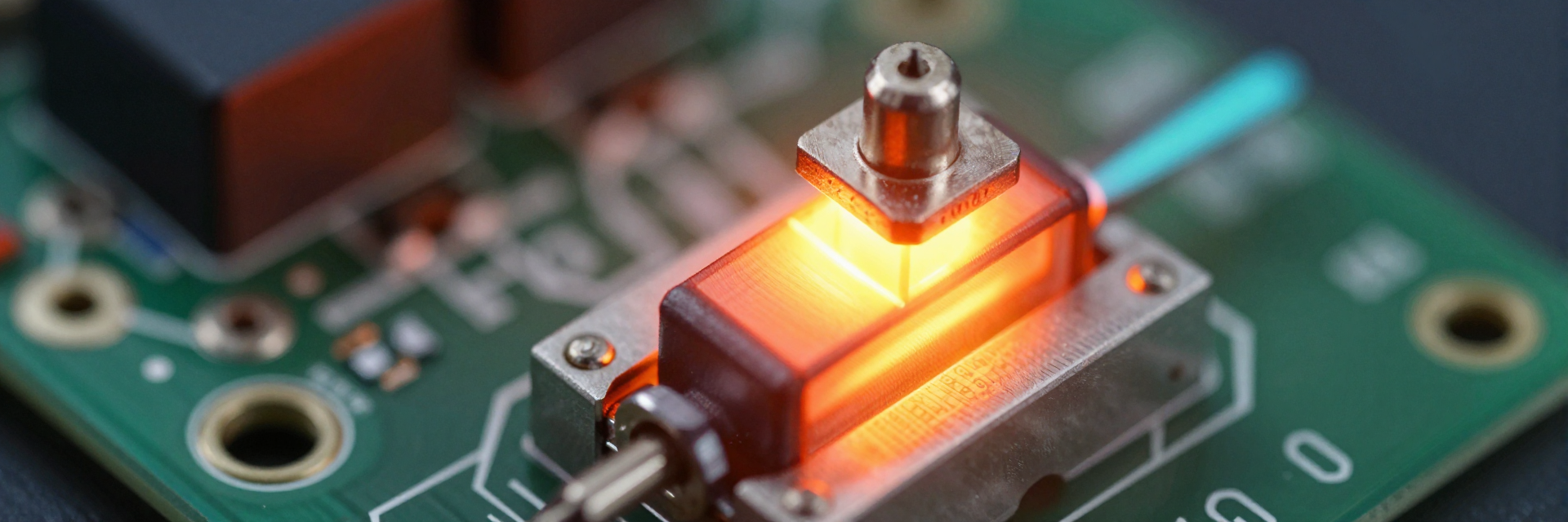
| Parameter | Specification | Design Impact |
|---|---|---|
| Nominal Resistance | 35 µΩ | Minimizes voltage drop and power loss |
| Tolerance | ±10% | Balances sensitivity vs. ADC noise floor |
| Power Rating | 36 W | High current handling for EV/Industrial apps |
| Construction | Metal Strip | Superior TCR stability vs. wirewound |
Resistance Value and Tolerance Impact on Signal Integrity
You must carefully evaluate the nominal resistance of this component, typically set at 35 µΩ with a ±10% tolerance. This extremely low resistance value is designed to minimize voltage drop across the shunt, thereby reducing power loss and heat generation during operation. However, maintaining a measurable signal level for Analog-to-Digital Converters (ADCs) requires balancing sensitivity against the noise floor. In high-current applications, a lower resistance reduces the signal amplitude, making it susceptible to electromagnetic interference. You need to ensure that the signal remains above the ADC’s least significant bit threshold while staying within safe operating limits.
Physical Dimensions and PCB Footprint Compatibility
The metal element construction and terminal design of the BAV-Z-R000035 are engineered for robust mechanical stability. When integrating this component into automated assembly lines, you should consider surface mount technology (SMT) advantages for density and speed versus through-hole reliability for high-vibration environments. The physical footprint must align with standard industry footprints to facilitate easy replacement or scaling. Furthermore, the mechanical robustness against vibration is paramount in automotive contexts, where loose connections can lead to catastrophic failure. Proper soldering techniques and secure mounting are essential to maintain electrical integrity throughout the product lifecycle.
Deep-Dive into 36W Shunt Resistor Thermal Behavior
Power Dissipation Limits and Derating Curves
To understand the true capabilities of this 36W Shunt Resistor, you must calculate actual power dissipation using the formula $P = I^2R$. At typical operating currents, the heat generated can quickly approach the rated limit if not properly managed. Interpreting the derating curve is crucial; as ambient temperature rises, the continuous power rating decreases significantly. You must ensure that the hotspot temperature remains below the maximum allowable limit to prevent permanent damage or accelerated aging. Ignoring these thermal constraints often leads to unexpected failures in high-load scenarios, compromising system safety and reliability.
Temperature Coefficient of Resistance (TCR) Analysis
The Temperature Coefficient of Resistance (TCR) defines how much the resistance value changes per degree Celsius. For this metal strip shunt, a low TCR is vital for maintaining measurement accuracy across varying thermal conditions. You should quantify the resistance change per degree to predict potential error margins in your system. Compared to wirewound alternatives, metal strip shunts generally offer superior TCR stability, especially during dynamic thermal cycles common in EV driving patterns. This stability ensures that current readings remain consistent, even when the resistor heats up rapidly during acceleration or regenerative braking phases.
Achieving High Accuracy in Current Sensing Designs
Minimizing Thermoelectric EMF Errors
Junction materials between different metals can generate thermoelectric voltages, introducing errors in precision measurements. You need to implement Kelvin connections to separate the current path from the voltage sensing path, effectively minimizing parasitic thermal gradients across sense terminals. Layout tips include keeping sense traces short and symmetric to reduce loop areas that pick up noise. By addressing these thermoelectric effects, you enhance the overall accuracy of the current sensing circuit, which is critical for battery state-of-charge estimation and protection algorithms.
Long-Term Stability and Drift Characteristics
Data on load life stability under continuous 36W stress indicates that material fatigue and oxidation can occur over ten years of operation. You must address these long-term drift characteristics by selecting components with proven endurance ratings. Periodic calibration strategies are recommended for safety-critical US market applications to account for any gradual resistance changes. Ensuring long-term stability helps maintain compliance with evolving industry standards and guarantees that the system operates safely throughout its intended lifespan.
Practical Implementation Guide for US Engineers
Optimal PCB Layout for Heat Management
Effective heat management requires specific copper pour and via stitching recommendations. You should maximize heat transfer away from the BAV-Z-R000035 by using large ground planes and multiple vias connected to internal layers. Thermal relief patterns help balance heat distribution without creating cold spots that could induce stress. Avoid placing sensitive analog traces near the shunt to prevent coupling of switching noise and thermal gradients. Proper layout practices significantly improve the thermal performance and longevity of the resistor.
Integration with Current Sense Amplifiers
Matching the shunt’s output voltage range with standard Current Sense Amplifier (CSA) input ranges is essential for accurate signal conditioning. You must consider filter design to mitigate switching noise from inverters, ensuring clean signals reach the ADC. A successful integration case study in a 400V battery pack monitor demonstrates how careful selection of CSA gain and bandwidth complements the shunt’s low-resistance profile. This holistic approach ensures reliable data acquisition for control systems.
Key Takeaways
- BAV-Z-R000035 Specs highlight the importance of low resistance and tight tolerance for minimal voltage drop.
- Thermal derating curves must be strictly followed to prevent overheating in 36W Shunt Resistor applications.
- Kelvin connections and proper PCB layout are critical for minimizing thermoelectric errors and maximizing accuracy.
- Understanding TCR stability ensures consistent performance across dynamic temperature ranges in EV systems.
Frequently Asked Questions
What is the main advantage of the BAV-Z-R000035 in EV designs?
The primary advantage lies in its combination of low resistance value and high power handling capability. It allows for precise current measurement with minimal energy loss, which is crucial for extending battery range in electric vehicles. Its robust thermal characteristics also ensure reliability under high-load conditions.
How does ambient temperature affect the 36W rating?
Ambient temperature directly impacts the continuous power rating through derating curves. As temperature increases, the maximum allowable power dissipation decreases to keep the component within safe operational limits. Engineers must account for worst-case thermal scenarios to avoid exceeding these limits.
Why are Kelvin connections necessary for this shunt resistor?
Kelvin connections separate the high-current path from the voltage sensing path, eliminating errors caused by trace resistance and contact impedance. This four-terminal setup ensures that the measured voltage accurately reflects only the drop across the resistive element, enhancing overall measurement precision.
What PCB layout techniques optimize heat management for the BAV-Z-R000035?
Effective heat management requires maximizing copper pour area and using multiple vias connected to internal ground planes. Thermal relief patterns help balance heat distribution without creating cold spots. Avoid placing sensitive analog traces near the shunt to prevent coupling of switching noise and thermal gradients.