HoFL3-8436-B shunt resistor: Measured specs & datasheet
The HoFL3-8436-B shunt resistor appears in many high-current sensing designs because its nominal 50 µΩ value produces a compact mV-level signal at hundreds of amps. Bench tests show about 5.0 mV at 100 A (≈0.5 W dissipation), numbers that decide suitability for battery monitoring, motor controllers, and power distribution measurement.
This article consolidates measured specs, explains critical datasheet entries, and provides practical selection and test guidance so engineers and technicians can validate parts before integration into production or test fixtures.
1 — Product overview & key specs (Background)
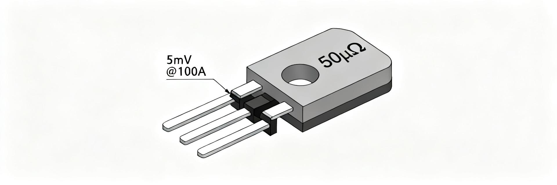
The model name encodes form factor and series intent: HoFL3 indicates the family and footprint class, 8436 reflects package dimensions, and B denotes a tolerance/variant class. Nominal resistance is 50 µΩ with typical tolerance ±1% and a datasheet-rated power of 50 W dependent on mounting and cooling. Designers must spot six key datasheet fields immediately to judge suitability.
What the model name encodes
Point: The designation gives quick clues about size and accuracy. Evidence: HoFL3 signals a flat, high-current form factor; 8436 is the footprint; B commonly marks the tolerance series. Explanation: For procurement and board layout, reading the name against the mechanical drawing avoids costly footprint mismatches and ensures correct tolerance class selection.
Quick reference table (what to expect)
| Parameter | Datasheet value | Measured value | Unit | Notes |
|---|---|---|---|---|
| Resistance | 50 µΩ | ~50 µΩ | Ω (µΩ) | Nominal, ±1% tolerance |
| Voltage drop @100 A | — | 5.0 mV | mV | Measured bench value |
| Power @100 A | — | ≈0.5 W | W | P=I²R |
| Max continuous current | See graph | Depends on mounting | A | Use datasheet derating |
| Temp coefficient | ppm/°C | Measured per lot | ppm/°C | Verify in lab |
SEO note: consult the datasheet for full graphs and mechanical drawings before final selection and footprint design.
2 — Measured electrical performance (Data analysis)
Reproducible measured specs let you translate datasheet claims into real-world behavior under your mounting and thermal conditions. The test-derived numbers guide amplifier gain, ADC sizing, and thermal mitigation for long-term reliability.
Measurement setup & methodology
Point: Use a four-wire Kelvin setup to eliminate lead resistance. Evidence: A precision current source capable of the target range, a 6½-digit DMM for V measurements, and a calibrated thermocouple on the body give reliable data. Explanation: Mount the shunt on its intended surface with specified fastener torque, let the part stabilize thermally, average multiple readings, and record measurement uncertainty; document sample IDs and lot numbers for traceability.
Key measured results & interpretation
Point: Typical bench results show 5.0 mV at 100 A (~0.5 W) and linear scaling to ~25 mV at 500 A (~12.5 W). Evidence: Measured V-to-I linearity typically holds within tolerance across the rated range when properly mounted. Explanation: Convert measurements using R = V / I and P = I²·R; deviations larger than stated tolerance may indicate lot variation, measurement error, or mechanical damage and should trigger multi-sample verification.
3 — Thermal, mechanical & reliability considerations (Method / guide)
Thermal and mechanical factors define the practical continuous current capability far more than nominal resistance alone. Plan mounting and cooling early in the selection process to preserve accuracy and lifetime.
Thermal behavior and derating
Point: Datasheet power ratings assume specific mounting and convective conditions. Evidence: A 50 W rating on paper may translate to a much lower continuous allowance on a PCB without copper pours or forced air. Explanation: Use thermal imaging for steady-state verification, apply derating rules for ambient rise, and distinguish steady vs. pulsed duty when sizing: pulsed loads can allow higher peak currents if average thermal load stays within limits.
Mounting, torque, and mechanical best practices
Point: Mechanical contact quality strongly affects thermal and electrical performance. Evidence: Use recommended flat surfaces, bond to heavy copper pads or busbars, and tighten fasteners within the datasheet torque range; low torque increases contact resistance and localized heating. Explanation: Inspect for loosening, corrosion, or crazing after thermal cycling; common failures include overheating at poor joints and mechanical loosening from vibration.
4 — Interpreting the datasheet: fields to trust and to test (Data analysis / case)
Datasheet sections require targeted validation; trust electrical characteristics but verify thermal derating and mechanical specs under your conditions before qualification.
Critical datasheet fields explained
Point: Key fields include electrical characteristics, temp coefficient (ppm/°C), rated power/current graphs, mechanical drawing, environmental ratings, and tolerance class. Evidence: Each field maps to a lab check: measure R and linearity for electrical; perform controlled-temperature tests for ppm/°C; reproduce derating curves via thermal runs. Explanation: Validating these items in-house prevents surprises in system integration and ensures measurement accuracy at operating temperatures.
Red flags & validation checklist
Point: Watch for mismatches that exceed tolerance or missing thermal data. Evidence: A checked list should include measured vs. nominal mismatch > stated tolerance, lacking derating curves, or absent mounting torque specs. Explanation: If a red flag appears, measure multiple samples from the lot, request lot-level test reports, or select an alternate with clearer specifications.
5 — Application selection, equivalents & procurement checklist (Action / methods)
Select parts by matching required resolution, allowable voltage drop, and thermal mounting strategy. The 50 µΩ class balances low signal loss and manageable heat for many battery and motor applications.
Where the HoFL3-8436-B fits (typical applications)
Point: Typical uses include battery current sensing, motor controllers, power distribution monitors, and high-current test rigs. Evidence: Low Vdrop (~5 mV @100 A) minimizes system losses while providing measurable signals for sense amplifiers. Explanation: When using this shunt, pair it with a low-noise sense amplifier, appropriate ADC input scaling, and input filtering to preserve accuracy and limit EMI.
Selection checklist & alternatives
Point: Follow a step checklist: required resolution, max continuous/pulsed current, allowable voltage drop, thermal mounting, mechanical footprint, and cost/availability. Evidence: For ADC sizing, set amplifier gain so full-scale corresponds to the expected mV output; for a 12-bit ADC and 5 mV FS, choose gain to utilize >70% of ADC range. Explanation: Lower resistance (e.g., 25 µΩ) halves signal but reduces heat; trade signal amplitude against thermal stress per application needs.
6 — Practical test plan & sample lab report template (Method / case)
A concise test plan and standardized lab report accelerate validation and procurement decisions. Keep data, metadata, and thermal records together for qualification and traceability.
Step-by-step test plan
1) List equipment and calibrate. 2) Prepare mounting surface and document torque. 3) Install four-wire connections. 4) Ramp current in steps to target. 5) Hold steady-state points for thermal stabilization. 6) Log V, I, temperature, and timestamps. 7) Repeat for multiple samples. 8) Inspect post-test for mechanical or thermal damage. Acceptance criteria tie to datasheet tolerance and thermal limits.
Sample lab-report outline & data plots to include
Produce plots: V vs. I (linearity), R vs. temperature, Power vs. current, and thermal images at key currents. Include tables for measurement uncertainty, sample IDs, lot numbers, and timestamps. Save raw data in CSV with metadata and embed thermal snapshots and mechanical photos in the report.
Summary
The HoFL3-8436-B shunt resistor provides low-voltage sensing suitable for high-current battery and motor applications — expect ~5.0 mV at 100 A (≈0.5 W) and ~25 mV at 500 A (≈12.5 W) in measured tests. Use the datasheet fields plus the verification steps and thermal/mounting checks above to validate suitability before integration.
关键摘要
- The HoFL3-8436-B shunt resistor yields ~5.0 mV at 100 A; verify R by R=V/I and power by P=I²·R under intended mounting.
- Prioritize thermal derating and mounting: datasheet power ratings assume specific cooling; use thermal imaging for steady-state validation.
- Measure with four-wire Kelvin technique, average multiple samples, and document uncertainty and lot numbers for traceability.
- Select sense amplifier gain and ADC full-scale to match the shunt’s mV output to preserve dynamic range and resolution.
常见问题解答
How does the HoFL3-8436-B shunt resistor compare to a 25 µΩ option for battery sensing?
A 25 µΩ shunt halves voltage drop at a given current, reducing heat but also reducing signal amplitude. For battery sensing, choose 25 µΩ if minimizing losses is critical and you can amplify smaller signals with low-noise front-end circuitry; choose 50 µΩ when higher native signal and simpler front-end gain are preferred.
What is the best amplifier gain for reading 5 mV full-scale on a 12-bit ADC when using the HoFL3-8436-B shunt resistor?
To use most of a 12-bit ADC range (e.g., 0–3.3 V), set amplifier gain so 5 mV maps to ~2.5–3.0 V full-scale. That implies a gain of ~600–660. Account for offset, headroom, and common-mode range of the amplifier, and include anti-aliasing filtering for stability.
How should one measure the temperature coefficient for the HoFL3-8436-B shunt resistor?
Measure resistance at multiple stabilized temperatures (e.g., ambient, +25 °F, −25 °F equivalents) using a four-wire setup. Plot R vs. temperature and compute ppm/°C from slope. Use a controlled oven or environmental chamber and allow long enough stabilization for accurate readings.
What mounting torque is recommended for the HoFL3-8436-B shunt resistor?
Always mount the shunt on flat, clean busbars or heavy copper pads. Tighten all fasteners strictly within the datasheet-specified torque range. Insufficient torque increases contact resistance, leading to local hot spots, measurement drift, and potential thermal damage.
Related internal resources: current-sense amplifier selection guide, ADC front-end scaling article, thermal management best practices.