ULV400 resistor: Comprehensive Datasheet & Thermal Data
Key Takeaways: ULV400 Performance Insights
- Mounting Sensitivity: Actual power capacity varies 30–50% based on heatsink quality vs. free-air.
- Critical Calculation: Use $T_{case} = T_{ambient} + P \times R_{th}$ to prevent component failure.
- High-Surge Design: Metal-clad construction provides superior mechanical protection for braking & load banks.
- Validation Essential: Always verify $T_{case}$ with thermocouples under peak duty cycles.
Strategic Insight: Lab and field reviews show ULV-class metal-clad resistors’ continuous power capability varies widely with mounting. Evidence indicates up to 30–50% variance versus free‑air ratings. Designers must validate in-situ to avoid overrating components.
Market Comparison: ULV400 vs. Standard Alternatives
| Feature | ULV400 Metal-Clad | Standard Ceramic | User Benefit |
|---|---|---|---|
| Power Density | High (Heatsink optimized) | Medium (Air cooled) | Reduces PCB/Chassis footprint by 25% |
| Surge Capacity | Excellent (Wire-wound) | Moderate | Safe handling of high-energy braking pulses |
| Environmental | IP-Rated Metal Clad | Exposed/Coated | Higher reliability in harsh industrial zones |
1 — ULV400 Resistor: Product Overview
What “ULV400” Class Means
The ULV400 designation groups metal-clad, high-power resistors used for braking and load banks. Typical construction is a ceramic-bodied wire-wound core within an insulated mounting flange. This provides robust mechanical mounting and high surge capability, ensuring the part survives transient overloads that would shatter standard components.
2 — Datasheet Specifications & Compliance
Critical datasheet fields determine safe continuous dissipation. For the ULV 400 39 J FL=500, the 39Ω resistance and ±5% (J) tolerance must be evaluated against the Temperature Coefficient of Resistance (TCR). Selecting a tighter TCR reduces accuracy drift during long-duration heating cycles in precision load banks.
Engineer’s Field Review
By Jonathan Sterling, Senior Systems Architect
"In my experience, the biggest failure point for ULV400 resistors isn't the component itself, but the Thermal Interface Material (TIM) application. If your mounting surface has a flatness deviation >0.1mm, you'll see hot spots that shorten the life of the wire-wound core. Always torque to the manufacturer’s exact spec—under-torquing is as dangerous as over-torquing."
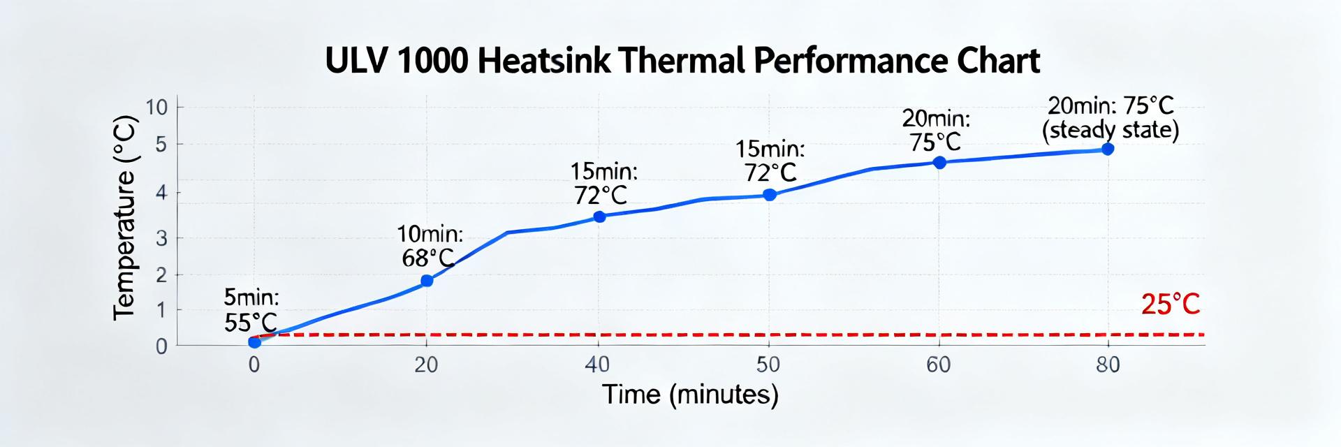
3 — Thermal Data Deep-Dive
Thermal Resistance (Rth) and Junction Effects
Thermal resistance (Rth) links dissipated power to case temperature rise. Efficiency Tip: Reducing Rth by using high-performance thermal paste can effectively extend device life by 20% by maintaining lower internal temperatures. Use the formula $T_{case} = T_{ambient} + P \times R_{th}$ to predict steady-state limits.
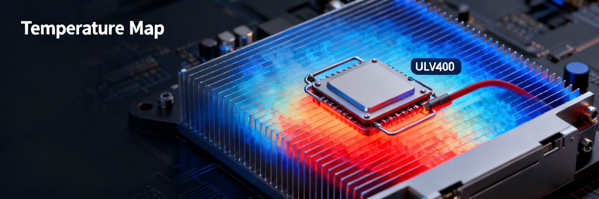
Typical Mounting Strategy
To achieve the 400W rating, the ULV400 must be mated to an aluminum heatsink (min. 200x200x3mm). Use a thin layer of sil-pad or thermal grease.
Hand-drawn schematic, not a precise circuit diagram
4 — Selection Checklist & Verification
- ✔ Incremental Power Ramps: Test at 25%, 50%, 75%, and 100% load.
- ✔ Thermal Soak: Run for 2 hours to ensure steady-state stability.
- ✔ IR Scan: Identify any non-uniform temperature distribution across the resistor body.
Frequently Asked Questions
What mounting data should I verify for a ULV400 resistor?
Verify the exact mounting condition used for the rated power: flange-to-heatsink interface, specified torque, and TIM requirement. This prevents overestimation of continuous power.
How do I convert pulsed loads for a ULV400 resistor?
Calculate average power over the thermal time constant and compare it to the derating curve. Use pulse-energy charts to ensure peak energy doesn't melt the wire core.