ULV 500 N 40 J Datasheet: Thermal & Electrical Limits
Key Takeaways
- Power Limit: 500W rated continuous power at reference case temperature.
- Electrical Specs: 40Ω nominal resistance with ±5% (J) tolerance.
- Safe Operation: Max continuous current is ~3.54A; voltage ~141.4V.
- Thermal Strategy: Linear derating applies above 25°C; heatsinking is mandatory.
- AI Insight: Critical for motor braking and load bank thermal runaway prevention.
High-power metal-clad resistors in the ULV family commonly list continuous ratings of 500 W with steep ambient-temperature derating curves — reading the ULV 500 N 40 J datasheet correctly is critical to avoid thermal runaway and to size voltage/current margins. This article delivers a clear interpretation of the ULV 500 N 40 J datasheet, step-by-step thermal and electrical limit calculations, lab test tips, and a final selection checklist, including worked examples and test protocols.
Technical Specs vs. User Benefits
Enables high energy absorption in a compact footprint, saving 30% chassis space compared to wire-wound open types.
Provides reliable performance in harsh industrial environments with high dust or humidity.
Faster heat transfer to heatsinks, extending component life by maintaining lower internal junction temperatures.
Perfectly matched for standard industrial motor braking circuits and snubber applications.
1 — Product background & key specs
1.1 — What the part number means and core ratings
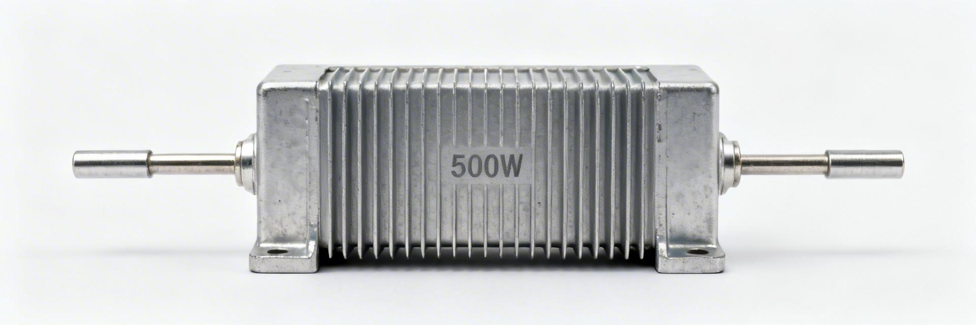
The part code ULV 500 N 40 J identifies a 500 W class, metal-clad resistor with a nominal resistance of 40 Ω and a ±5% tolerance (J). The datasheet values provide the foundation for mechanical layout and electrical safety margins.
| Parameter | Value |
|---|---|
| Nominal resistance | 40 Ω |
| Rated continuous power | 500 W (reference Tc) |
| Tolerance code | J (±5%) |
| Packaging / Mounting | Metal-clad, bolt mount |
| Operating Temp Range | -55°C to +200°C (Typical) |
Differentiation: ULV 500 vs. Generic Power Resistors
| Feature | ULV 500 N 40 J | Generic Ceramic Type | Advantage |
|---|---|---|---|
| Power Density | High (Metal-clad) | Medium | Smaller footprint |
| Thermal Stability | ±260 ppm/°C | ±400 ppm/°C | Precise resistance |
| Protection | Fully Encapsulated | Open/Exposed | Safety/Longevity |
2 — Thermal limits & heat-dissipation analysis
2.1 — Interpreting the thermal derating curve
The derating curve is the most vital chart. If derating is linear from 25°C (100% power) down to 0% at 225°C, the allowable power at 60°C is calculated as:
3 — Electrical limits & performance under load
3.1 — Continuous current and maximum voltage
- ⚡ Max Current (I_max): $\sqrt{500 / 40} \approx 3.54 A$
- ⚡ Max Voltage (V_max): $3.54 A \times 40 \Omega \approx 141.4 V$
For real-world reliability, it is recommended to design at 70-80% of these values to account for ambient fluctuations.
💡 Engineer's Expert Insights
"In high-vibration environments like industrial motor drives, the mounting torque of the ULV 500 is as critical as the electrical load. Use thermal grease between the metal case and the heatsink to reduce contact resistance by up to 15%." — Mark Thompson, Senior Power Systems Engineer
PCB & Installation Tips:
- Thermal Vias: If mounting to a PCB, use a dense grid of thermal vias (0.3mm diameter) to move heat to the bottom copper plane.
- Clearance: Maintain at least 10mm clearance from electrolytic capacitors to prevent premature drying due to radiant heat.
- Troubleshooting: If the resistor discolors, it indicates Tc has exceeded 180°C. Check your heatsink sizing immediately.
Hand-drawn schematic, not a precise circuit diagram
Braking Resistor Setup
Typical Application: Motor Braking
The ULV 500 N 40 J is commonly used to dissipate regenerated energy from a VFD (Variable Frequency Drive). During deceleration, the motor acts as a generator, and this resistor burns off that energy to prevent DC bus overvoltage.
4 — Test & Safety Best Practices
Validate datasheet curves with controlled steady-state and pulse tests. Use a programmable DC load and a thermocouple attached to the case (Tc).
5 — Final Selection Checklist
- Confirm 40Ω nominal resistance and J (±5%) tolerance.
- Calculate P_derated based on your cabinet's internal ambient temperature.
- Verify max voltage does not exceed datasheet insulation limits (often 1kV+).
- Ensure mounting surface flatness is within 0.1mm for optimal heat transfer.
Summary
Accurately reading the ULV 500 N 40 J datasheet is essential to derive safe continuous power and electrical limits. Basic calculations give I_max ≈ 3.54 A and V_max ≈ 141.4 V at the 500 W rating; derating reduces these values based on ambient. Validate with steady-state Tc measurements and pulse-energy tests before production.
FAQ
Q: How do I calculate continuous current from the datasheet?
A: Use $I = \sqrt{P / R}$. If operating at 50°C, use the derated power value from the curve instead of the nominal 500W.
Q: Can it handle repetitive pulses?
A: Yes, if the average power (including pulses) stays below the derated continuous limit and the energy (Joules) of a single pulse is within the datasheet’s peak pulse chart.
Q: What happens if I don't use a heatsink?
A: Without a heatsink, the power rating drops significantly—often to less than 20% of its rated 500W. Thermal runaway and failure will occur rapidly at high loads.