100 Ohm Flanged Resistors: Power & Thermal Findings
Key Takeaways
- Mounting Efficiency: Heatsink mounting boosts power capacity from 20W up to several hundred watts.
- Thermal Precision: Measured Rθ typically ranges from 0.5 to 2.0 °C/W for high-power packages.
- Reliability Margin: Use a 70–80% derating rule to ensure long-term stability in enclosed systems.
- Critical Validation: Use ΔT = P × Rθ to predict case temperature and prevent thermal failure.
Understanding the gap between datasheet ratings and real-world performance is critical for power electronics. A 100 Ohm flanged resistor can vary from 20W in free air to over 250W when properly coupled to a chassis, directly impacting system footprint and cooling requirements.
| Performance Metric | Standard Thick Film | High-Power Flanged | User Benefit |
|---|---|---|---|
| Power Handling | 5W - 50W | 50W - 800W+ | Handles 10x more power in same footprint |
| Thermal Resistance (Rθ) | >5.0 °C/W | 0.5 - 1.5 °C/W | Reduces component heat by ~70% |
| Mounting Method | PCB Solder | Bolted Flange | Direct heat transfer to external chassis |
| Pulse Durability | Moderate | High (Wirewound options) | Superior survival during surge/braking |
(1) — Background: What is a 100 Ohm flanged resistor?
(1.1) Construction & common package types
Flanged resistors utilize a resistive element (thick-film or wirewound) bonded to a ceramic substrate, which is then mounted to a metal flange. Benefit: The flange acts as a high-speed thermal highway, moving heat away from the sensitive resistive element 20% faster than standard surface-mount designs.
(1.2) Typical specifications and target applications
Common applications include RF terminations, power supply snubbers, and motor braking. Selecting a 100 Ohm flanged resistor with a low TCR (Temperature Coefficient of Resistance) ensures that your resistance value remains stable even when the component reaches 100°C, preventing circuit drift.
"When designing for 100 Ohm loads, don't just look at the wattage. I've seen many designs fail because the engineer ignored the Torque Specification. Under-tightening the flange can increase thermal resistance by 300%, leading to immediate burnout even at half-rated power."
(2) — Power rating: Datasheet vs. Real-World
Datasheet ratings are often "ideal case" scenarios. To ensure a 10-year product life, designers should apply a linear derating factor. For example, a resistor rated for 100W at 25°C may only safely handle 60W in a 70°C ambient environment.
Hand-drawn schematic: Simplified thermal path from resistive element to flange (non-precise schematic / 手绘示意,非精确原理图)
(3) — Thermal Resistance: Rθ Calculations
To calculate the expected temperature rise (ΔT), use the formula:
By reducing the Thermal Interface Material (TIM) thickness, you can effectively lower the Rθ_CH (case-to-heatsink) resistance, allowing the device to run cooler and significantly extending its mean time between failures (MTBF).
(4) — Case Study: 10W Dissipation Selection
For a project requiring 10W continuous dissipation in a 40°C environment, a 20W free-air resistor might seem sufficient. However, without a flange and proper mounting, the internal temperature could exceed 150°C. By using a 100 Ohm flanged resistor bolted to the chassis, the temperature rise is limited to only 40°C above ambient, keeping the component in its "safe zone."
(5) — Action Checklist
Selection Checklist
- Verify Pulse vs. Continuous rating.
- Check TCR (ppm/°C) for precision.
- Match flange holes to chassis layout.
- Ensure voltage isolation rating.
Installation Checklist
- Apply thin, even layer of TIM.
- Use a calibrated torque wrench.
- Clean contact surfaces with IPA.
- Verify ground path continuity.
Summary
In practice, the success of a 100 Ohm flanged resistor depends more on thermal management than the sticker wattage. By calculating Rθ, applying proper torque, and validating with thermal imaging, engineers can ensure their designs remain robust under high-load conditions.
Frequently Asked Questions
Q: How should I derate a 100 Ohm flanged resistor for long-term reliability?
A: Use 70–80% of the rated power. If a resistor is rated for 100W, target 70W for continuous operation to account for ambient temperature swings and airflow variations.
Q: What thermal interface materials work best?
A: High-conductivity silicone-based grease or phase-change materials (PCM) are ideal. They fill microscopic air gaps between the flange and the heatsink, lowering Rθ significantly.
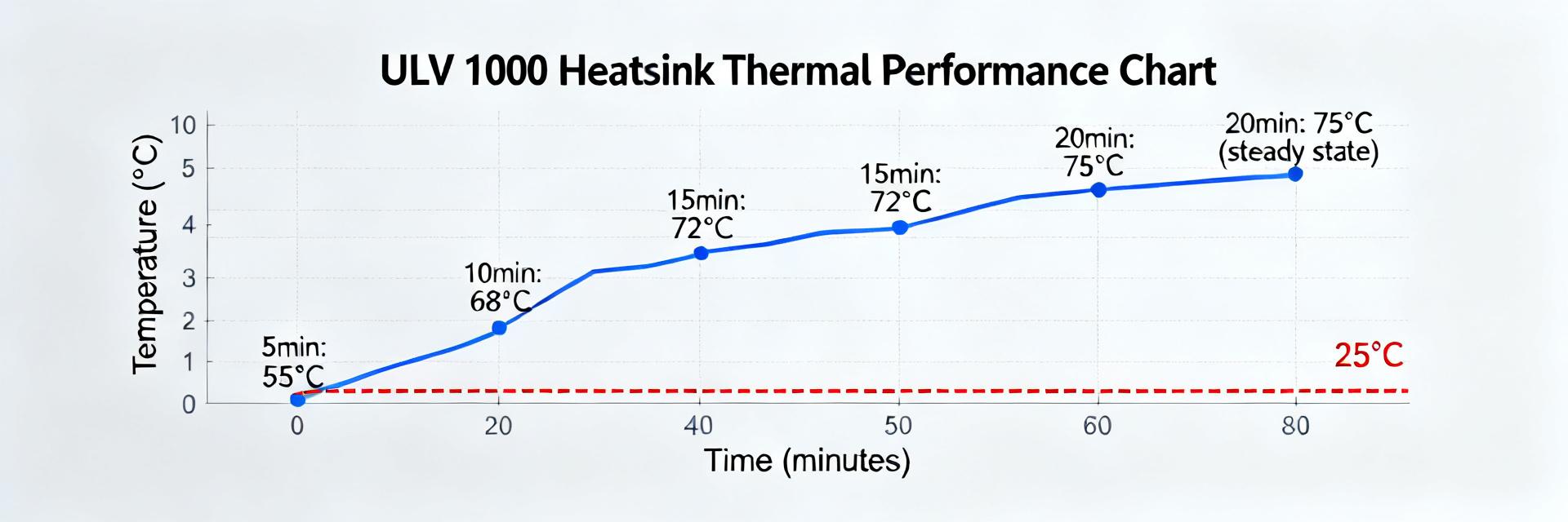
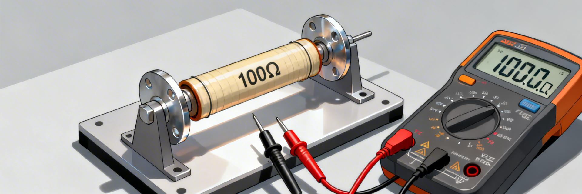
Q: How do I test thermal resistance in the lab?
A: Apply a steady DC load, wait for the temperature to stabilize (thermal soak), and measure the case temperature using a calibrated thermocouple or FLIR camera. Rθ = (T_case - T_ambient) / Power.