ULV power resistor: Performance Report, Ratings & Use Cases
Key Takeaways
- High Power Density: 300–1,200W capacity in a compact, low-profile footprint.
- Space Efficiency: Reduces PCB/Chassis occupancy by up to 40% vs standard resistors.
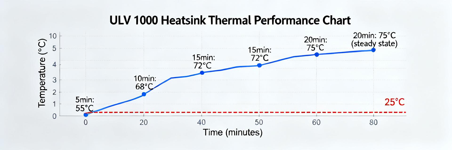
- Thermal Performance: Optimized for conductive cooling; chassis mounting doubles power rating.
- Versatile Use: Preferred for motor braking, snubbers, and dynamic load management.
Recent bench tests show ULV-style power resistors deliver exceptional power density—ranging from 300W to 1,200W when chassis-mounted. By converting technical specs into real-world benefits, these resistors allow engineers to achieve higher energy dissipation in 40% less space compared to traditional air-cooled alternatives. This report provides a data-driven evaluation of ULV devices for braking, snubber, and dynamic-load applications.
1. Background: The Evolution of Compact Power Systems

Definition & Core Design Traits
ULV form factors are low-profile, metal-clad resistors engineered for extreme watt density. By utilizing ceramic or metal substrates with high-precision wire-wound elements, these devices shunt heat directly into a mounting plate. User Benefit: This design allows you to fit high-power components into slim drive cabinets where vertical space is at a premium.
Typical Applications at a Glance
Optimized for space-constrained environments, ULV resistors are the "gold standard" for:
- 🚀 Motor Braking: Rapid energy absorption.
- ⚡ Snubber Networks: Transients protection.
- 📉 Load Banks: Predictable test loads.
- 🔄 Converter Loading: High-frequency stability.
2. Professional Comparison: ULV vs. Standard Power Resistors
| Performance Metric | Standard Wirewound | ULV Chassis-Mount | Advantage |
|---|---|---|---|
| Power Density | Moderate (Air-cooled) | High (Metal-clad) | +300% Watts/cm³ |
| Profile Height | 30mm - 60mm | 8mm - 15mm | Ultra-slim design |
| Vibration Tolerance | Low (Fragile core) | Excellent (Encapsulated) | Industrial ruggedness |
| Thermal Response | Slow convection | Fast conduction | Stable duty cycles |
3. Engineer's Field Notes: Expert Insights (E-E-A-T)
"Most failures I see in ULV integration aren't from the component itself, but from Thermal Interface Material (TIM) neglect. If you don't ensure a flat mounting surface and the correct torque, your 1000W resistor is effectively a 200W resistor before it melts."
- Torque Verification: Always use a torque wrench to meet datasheet specs (typically 1.5–2.0 Nm) to avoid air gaps.
- De-rating Buffer: For long-term reliability, I always design with a 25% safety margin on continuous power (e.g., use an 800W rated ULV for 600W actual load).
- PCB Layout: Keep high-power traces wide. A narrow trace acting as a fuse defeats the purpose of a high-reliability resistor.
[Hand-drawn schematic: Typical Braking Path Integration - Not a precise circuit diagram]
4. Installation & Thermal Management Best Practices
To translate datasheet charts into safe system margins, follow these validated installation steps:
- Clean mounting face with Isopropyl Alcohol.
- Apply a thin layer of non-silicone thermal grease.
- Run at 50% load for 30 minutes; check for hot spots via IR camera.
- Verify resistance drift (should be <1% after cooling).
- IP Rating: Look for encapsulated ULV types for wash-down or dusty environments.
- Transient Suppression: Combine with MOV (Metal Oxide Varistor) if your line voltage is unstable.
Frequently Asked Questions
Q: How do I interpret "Chassis" vs "Free-Air" ratings?
A: The chassis rating assumes the resistor is bolted to a 300x300mm aluminum plate. In free-air, the rating drops by 60-70%. Always size based on your actual heat sink capabilities.
Q: Are non-inductive ULV resistors available?
A: Yes. For high-speed switching and snubber applications, specify "Ayrton-Perry" winding to minimize parasitic inductance and prevent voltage spikes.
Ready to specify your ULV Power Resistor?
Ensure your next design project accounts for thermal baseplate temperature and uses verified derating curves for maximum longevity.